
A photocatalytic air purification device

An air purification device and photocatalysis technology, which is applied in air conditioning systems, space heating and ventilation, space heating and ventilation details, etc., can solve the problem of low purification efficiency of gaseous pollutants, uneven light intensity of photocatalysts, and air purification devices. high power consumption

Active Publication Date: 2021-04-20
北京阳光凯特科贸有限公司
View PDF5 Cites 0 Cited by
  • Summary
  • Abstract
  • Description
  • Claims
  • Application Information

AI Technical Summary

Problems solved by technology

[0005] 1. Before the air undergoes photocatalytic purification of gaseous pollutants, it has experienced the filtration of PM2.5 particles, and then passed through the mesh plate photocatalysis, there is a large wind resistance, and the power consumption of the air purification device is high. Under long-term use, the net Dust and dirt are attached to the holes, which will increase the wind resistance and further increase the power consumption of the air purification device
[0006] 2. The photocatalyst attached to the flat mesh combined with single-sided illumination, the light source utilization efficiency is not only half, but also the light intensity irradiated on the photocatalyst is uneven, resulting in low purification efficiency of gaseous pollutants

Method used


Image

  • A photocatalytic air purification device
  • A photocatalytic air purification device
  • A photocatalytic air purification device

Examples


Embodiment Construction

[0033] Embodiments of the technical solutions of the present invention will be described in detail below in conjunction with the accompanying drawings. The following examples are only used to illustrate the technical solution of the present invention more clearly, so they are only examples, and should not be used to limit the protection scope of the present invention.

[0034] It should be noted that, unless otherwise specified, the technical terms or scientific terms used in this application shall have the usual meanings understood by those skilled in the art to which the present invention belongs.

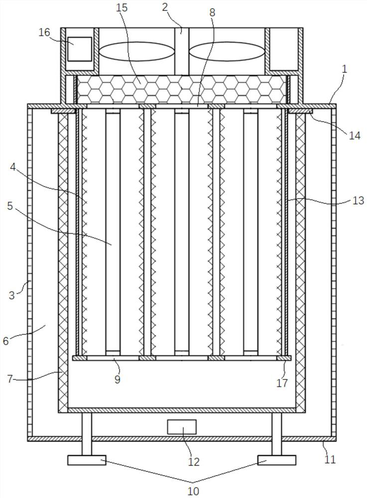
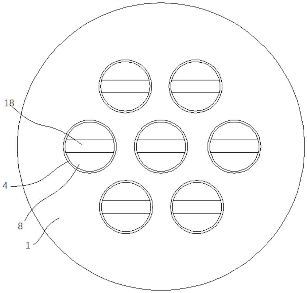
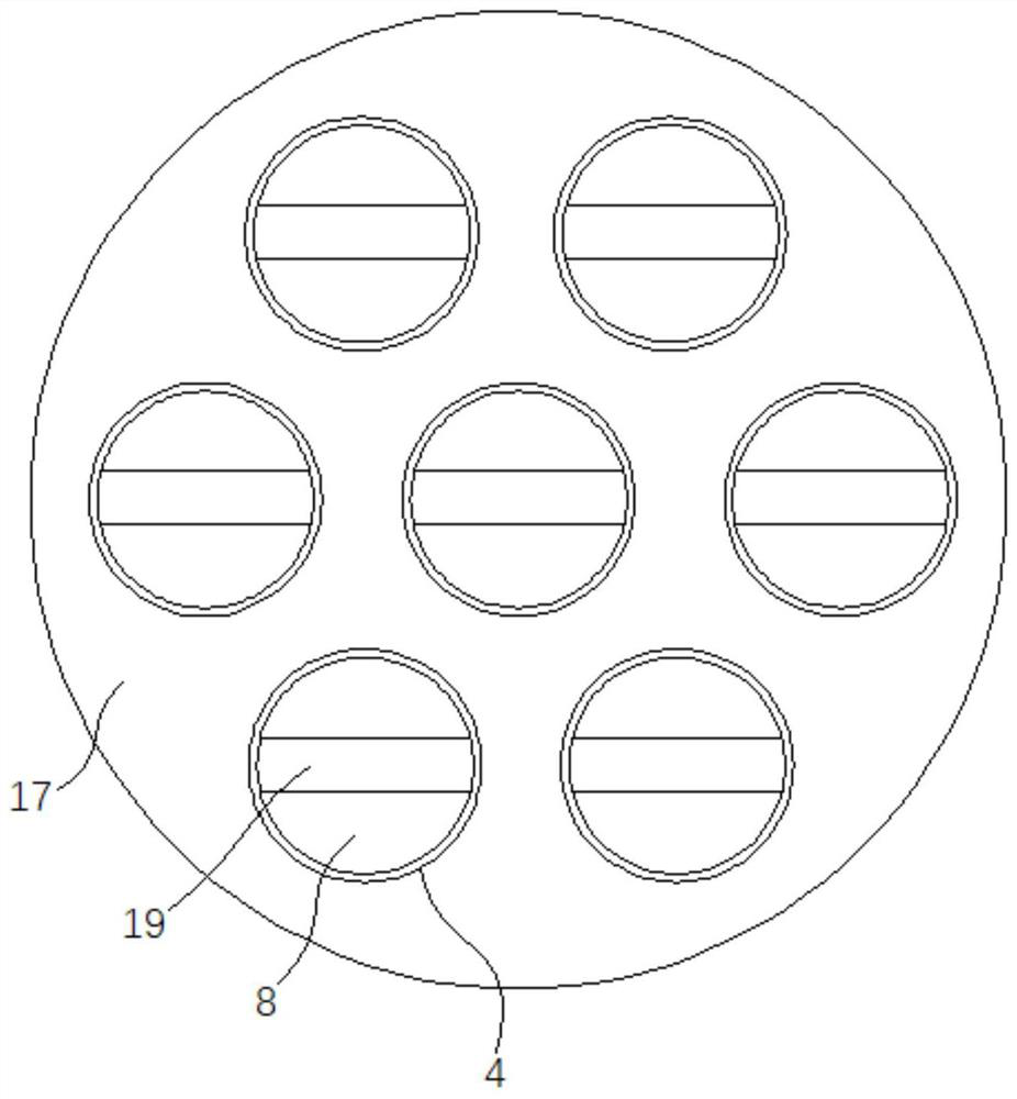
[0035] Such as Figure 1 to Figure 3 As shown, a photocatalytic air purification device includes a housing 1, a fan 2, a barrel-shaped PM2.5 filter 7, and a photocatalytic purification module;

[0036] The side wall of the shell 1 is provided with a coarse filter 3, and the barrel-shaped PM2.5 filter 7 is vertically installed in the shell 1, and its top opening is sealed with th...


PUM


Abstract

The invention discloses a photocatalytic air purification device, which comprises a casing, a fan, a barrel-shaped PM2.5 filter, and a photocatalytic purification module; the side wall of the casing is provided with a coarse filter, and the barrel-shaped PM2.5 filter is installed vertically In the casing, the top opening is sealed with the casing; the photocatalytic purification module includes a plurality of catalyst loading cylinders with photocatalysts on the inner wall and lamp tubes coaxially arranged in each catalyst loading cylinder, and each catalyst loading cylinder is installed vertically In the inner cavity of the barrel-shaped PM2.5 filter, the lower end of each catalyst loading cylinder is connected to the inner cavity of the barrel-shaped PM2.5 filter. The top of the shell is respectively provided with a vent A corresponding to the upper end of each catalyst loading cylinder. The upper edge of the load tube is connected to the edge of the corresponding vent A; the fan is installed on the top of the casing, and its air inlet is connected to all the vents A. The invention can greatly reduce wind resistance in the air purification process to reduce power consumption, has high light source utilization rate, uniform light intensity, and high purification efficiency of gaseous pollutants.

Description

technical field [0001] The invention relates to an air purification device, in particular to a photocatalytic air purification device. Background technique [0002] In recent years, the problem of air pollution in our country is more serious, especially the pollution of indoor air is becoming more and more prominent. In addition to solid particulate matter PM2.5, gaseous pollutants such as formaldehyde, toluene, ammonia, etc. not only produce peculiar smell, but also affect people's health if inhaled for a long time. It is urgent to purify the polluted air, so all kinds of air The purification device came into being. [0003] Traditional air purification devices are mainly equipped with PM2.5 filters to filter solid particles in the air, and have no effect on purifying gaseous pollutants. Some air purification devices are equipped with activated carbon layers to physically adsorb gaseous pollutants, which can reduce the concentration of indoor gaseous pollutants to a certa...

Claims


Application Information

Patent Timeline
Patent Type & Authority Patents(China)
IPC IPC(8): F24F8/108F24F8/40F24F8/22F24F13/28F24F11/89
CPCF24F13/28F24F11/89F24F8/10F24F8/192F24F8/22F24F8/40
Inventor 潘锋
Owner 北京阳光凯特科贸有限公司
Learn More