Heat sink and heat dissipation member including the heat sink

A heat sink and glass cloth technology, applied in the direction of electrical components, semiconductor devices, electric solid devices, etc., can solve the problems of heat sink thermal conductivity reduction, insulation damage, low thermal conductivity, etc., to achieve efficient punching processing, The effect of high insulation and high thermal conductivity

Active Publication Date: 2021-03-05
DENKA CO LTD
View PDF17 Cites 0 Cited by
  • Summary
  • Abstract
  • Description
  • Claims
  • Application Information

AI Technical Summary

Problems solved by technology

The thermal conductivity of the polyimide film material itself is low, and the heat transfer between the thermally conductive filling materials is blocked by the polyimide film, so the thermal conductivity of the heat sink is reduced, and the cost is also high, so it is not preferred to use
[0006] Furthermore, attempts were made to improve heat dissipation by reducing the thickness of the heat sink, but the insulation was inevitably impaired, so the above-mentioned problems could not be solved.

Method used


Image

  • Heat sink and heat dissipation member including the heat sink
  • Heat sink and heat dissipation member including the heat sink

Examples


Embodiment 1

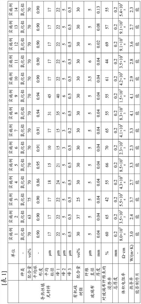
[0045] Polyorganosiloxane base polymer (Dow Corning Toray Co., Ltd. trade name "CF3110") and crosslinking agent (Dow Corning Toray Co., Ltd. trade name "RC-4") were mixed in a weight ratio They were mixed at a ratio of 100:1 to obtain a silicone resin component. The obtained silicone resin component and alumina powder as a thermally conductive filler were filled at the volume % shown in Table 1 and Table 2, and mixed with a mixer for 15 hours to prepare an alumina-containing silicone composition.

[0046] The average sphericity of the thermally conductive filler (alumina powder) was measured as follows using a flow particle image analyzer (manufactured by Sysmex Corporation, trade name "FPIA-3000"). The projected area (A) and perimeter (PM) of the particles were determined from the particle images. Assuming (B) is the area of ​​a perfect circle corresponding to the circumference (PM), the sphericity of the particle can be expressed as A / B. Therefore, if it is assumed to be a...

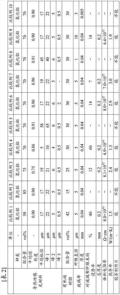
Embodiment 2~14 and comparative example 1~10

[0050] Except having adopted the conditions shown in Tables 1-2, it carried out similarly to Example 1, and produced the heat sink.

[0051] (evaluate)

[0052] The following evaluation items (1)-(5) were performed about the heat sink of the trial-produced Examples 1-14 and Comparative Examples 1-10. The results are shown in Tables 1-2. It should be noted that, for an example in which a heat sink cannot be normally produced in a sheet form (caused by looseness or surface cracks), "whether the sheet can be produced" is described as "impossible".

[0053] (1) Volume resistivity

[0054] The volume resistivity was evaluated according to the method described in JIS C 2139:2008. As a measuring device, a superinsulator (trade name "SM-10E" manufactured by Hioki Electric Co., Ltd.) was used.

[0055] (2) thermal conductivity

[0056] For thermal conductivity (H; unit W / (m·K)), the evaluation was performed in the thickness direction of the heat sink. According to thermal diffusi...


PUM

PropertyMeasurementUnit
particle sizeaaaaaaaaaa
thicknessaaaaaaaaaa
diameteraaaaaaaaaa

Abstract

A heat sink characterized in that it has a structure in which layers of a silicone composition containing aluminum oxide are laminated on both sides of a glass cloth of a reinforcing layer, and the inside of the glass cloth contains a silicone composition, wherein the average sphericity of aluminum oxide is 0.85 or more, in the frequency particle size distribution of alumina, there are extremely large peaks in the region of 15-50 μm, 1-7 μm and 0.1-0.8 μm, the average particle size of alumina is 7-50 μm, the organic silicon composition The content of alumina in the glass is 62-78% by volume, the content of silicone resin is in the range of 22-38% by volume, and the glass cloth is a woven glass fiber bundle made of bundled glass filaments. The impregnation rate of the silicon composition to the glass fiber bundle is 20% or more.

Description

technical field [0001] The present invention relates to a heat radiation sheet that is closely adhered to an interface between an electronic component and a heat dissipation portion such as a heat sink or a circuit board in order to cool a heat-generating electronic component. Background technique [0002] Heat sinks are usually formed by coating a silicone composition containing a thermally conductive filler (hereinafter referred to as a silicone composition) on both sides of a reinforcing layer such as glass cloth. Due to its high thermal conductivity, electrical insulation, and handleability Therefore, in the field of electronic materials, in order to cool the electronic components that generate heat, it is used in close contact with the interface between the electronic component and the heat dissipation part such as a heat sink or a circuit board. For example, Patent Documents 1 to 5 below disclose heat sinks in which a heat conduction layer is provided on a reinforcemen...

Claims


Application Information

Patent Timeline
Patent Type & Authority Patents(China)
IPC IPC(8): H05K7/20C08J5/04H01L23/373
CPCC08J5/04H01L23/3737H01L23/42C08J5/043C08J2383/04
Inventor 和田光祐山县利贵金子政秀谷口佳孝
Owner DENKA CO LTD
Why Eureka
Try Eureka