
A Jet Printing Equipment Suitable for Selective Melting Forming under Wide Temperature Gradient

A printing equipment and selective technology, applied in metal processing equipment, processing and manufacturing, manufacturing tools, etc., can solve the problems of low production efficiency, difficult temperature control, poor sample accuracy, etc., to avoid shrinkage and shrinkage, shortening Time required, effect of increasing density and mechanical properties

Active Publication Date: 2020-10-02
HUAZHONG UNIV OF SCI & TECH
View PDF8 Cites 0 Cited by
  • Summary
  • Abstract
  • Description
  • Claims
  • Application Information

AI Technical Summary

Problems solved by technology

The jet printing and printing equipment solves the existing technical problems such as low production efficiency, poor sample precision and difficult temperature control of the working environment. By designing the heating roller module and structural design, the degree of automation, printing speed and precision are improved, Good molding quality, low cost of equipment and materials, good applicability

Method used


Image

  • A Jet Printing Equipment Suitable for Selective Melting Forming under Wide Temperature Gradient
  • A Jet Printing Equipment Suitable for Selective Melting Forming under Wide Temperature Gradient
  • A Jet Printing Equipment Suitable for Selective Melting Forming under Wide Temperature Gradient

Examples


Embodiment Construction

[0025] In order to make the object, technical solution and advantages of the present invention clearer, the present invention will be further described in detail below in conjunction with the accompanying drawings and embodiments. It should be understood that the specific embodiments described here are only used to explain the present invention, not to limit the present invention. In addition, the technical features involved in the various embodiments of the present invention described below can be combined with each other as long as they do not constitute a conflict with each other.

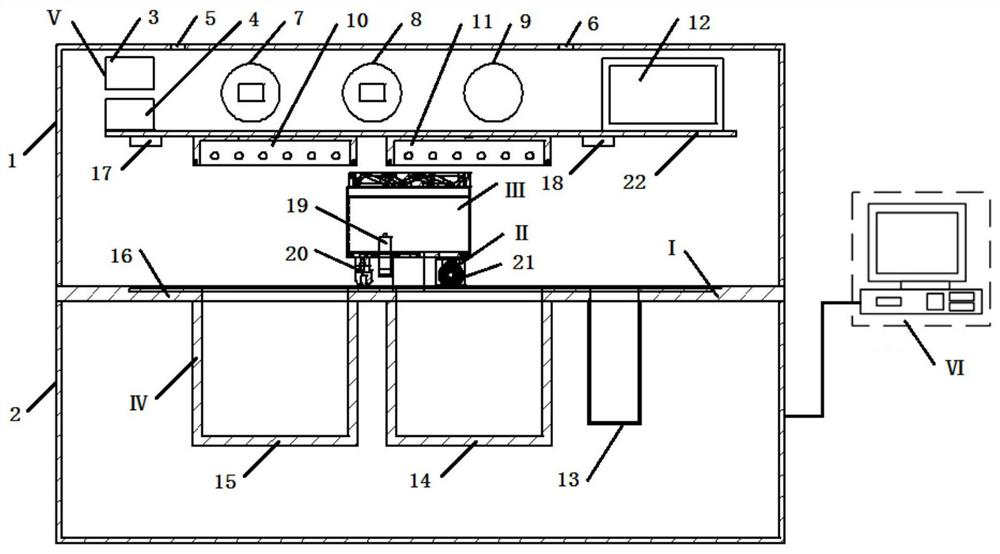
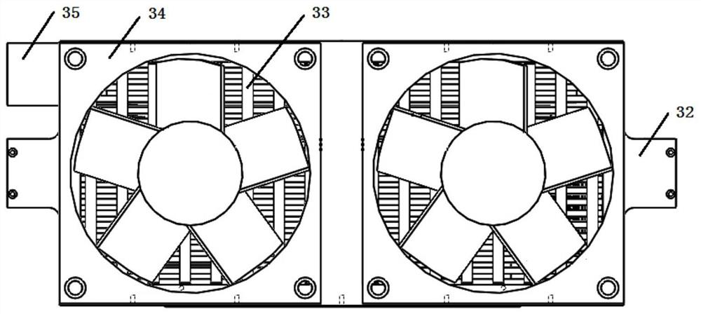
[0026] see figure 1 , figure 2 and image 3 , the inkjet printing equipment suitable for selective melting and forming under wide temperature gradient provided by the present invention, said inkjet printing equipment includes an upper cover body 1, a lower cover body 2, a support plate 22, a water cooling tube 33, and two fans 34 , powder spreading assembly I, heating assembly II, spray prin...


PUM


Abstract

The invention belongs to the industrial-grade powder rapid manufacturing molding related technology field and discloses spray printing equipment suitable for selective melting molding under a wide temperature gradient. The spray printing equipment comprises an upper cover body, a lower cover body, a powder laying component, a spray printing component and a heating component, wherein the spray printing component and the heating component are connected, and the upper cover body is connected with a powder laying base plate to form a closed space used for containing components; the heating component includes a first directional heat radiator, a second directional heat radiator and a heating roller module; and the first directional heat radiator and the second directional heat radiator are connected to the upper cover body and are used for heating a powder in a powder laying area and the powder in a working area so as to heat the powder to be in a glassy state; the heating roller module isconnected to the spray printing component and the powder in the working area is compacted and is further heated at the same time, and a part, sprayed to an adhesive, of the powder in the working areais melted and cured. Precision is improved, forming quality is good, and applicability is high.

Description

technical field [0001] The invention belongs to the technical field related to the rapid manufacturing and molding of industrial-grade powder, and more specifically relates to a jet printing equipment suitable for selective melting and molding under a temperature gradient. Background technique [0002] Laser and other high-energy beam non-metallic 3D printing (namely selective laser melting SLM) is widely used in aerospace, mold and other fields, and has attracted the most attention, but there are still significant problems of low efficiency and high cost. Jet printing 3D printing uses nozzle jet forming, The advantages of high efficiency and low cost are obvious. [0003] At present, in the current powder 3D printing device, the printing unit works at room temperature, and the non-metallic materials are always in a powder state, and the printing unit sprays adhesive to the printing work area while moving. In this case, on the one hand, after the sample is formed by bonding...

Claims


Application Information

Patent Timeline
Patent Type & Authority Patents(China)
IPC IPC(8): B29C64/112B29C64/20B29C64/295B29C64/386B29C64/393B29C64/214B29C64/153B33Y30/00B33Y50/00B33Y50/02
CPCB29C64/112B29C64/153B29C64/20B29C64/214B29C64/295B29C64/386B29C64/393B33Y30/00B33Y50/00B33Y50/02
Inventor 魏青松胡敏蕙蔡道生叶春生毛贻桅李敬文张净凯南亚琪
Owner HUAZHONG UNIV OF SCI & TECH
Learn More