Large-particle solder feeder

A large particle feeder technology, applied in welding equipment, auxiliary welding equipment, welding/cutting auxiliary equipment, etc., can solve the problems of destroying the structure of large particle alloy materials, failing to meet process requirements, intermittent and unstable feeding, etc. , to achieve accurate flow control, expand the scope of use and use occasions, and compact structure

Pending Publication Date: 2020-03-24
上海多木实业有限公司
View PDF6 Cites 0 Cited by
  • Summary
  • Abstract
  • Description
  • Claims
  • Application Information

AI Technical Summary

Problems solved by technology

[0010] In the composite surfacing process, comparatively speaking, the diameter of the added alloy particles is larger, much larger than the diameter of the base powder (80-300 mesh), generally between 1mm and 5mm, and most of them are irregular in shape, with Angular, sharp, therefore, the existing powder feeder cannot achieve a stable feeding of this type of solder
[0011] The powder feeder in the prior art is to precisely control the one-time flow rate at the discharge port. The powder feeder designed according to the required flow rate often has a small diameter of the discharge port. This small-caliber feeder When the powderer transports solder containing irregular large-grained alloy materials, it will often be blocked at the narrow part of the discharge port, resulting in intermittent and unstable feeding; if the flow rate is enlarged to solve the blockage, it cannot meet the small flow rate of welding. Process requirements for materials
[0012] In addition, the screw or impeller in the screw powder feeder and impeller feeder in the prior art will squeeze, roll and crush the large-grained alloy material, destroying the structure of the large-grained alloy material in the material, Lose its function; and the scraper of the scraper type feeder is easy to trap the debris of the particles, resulting in failure to work normally

Method used


Image

  • Large-particle solder feeder
  • Large-particle solder feeder
  • Large-particle solder feeder

Examples


Embodiment 1

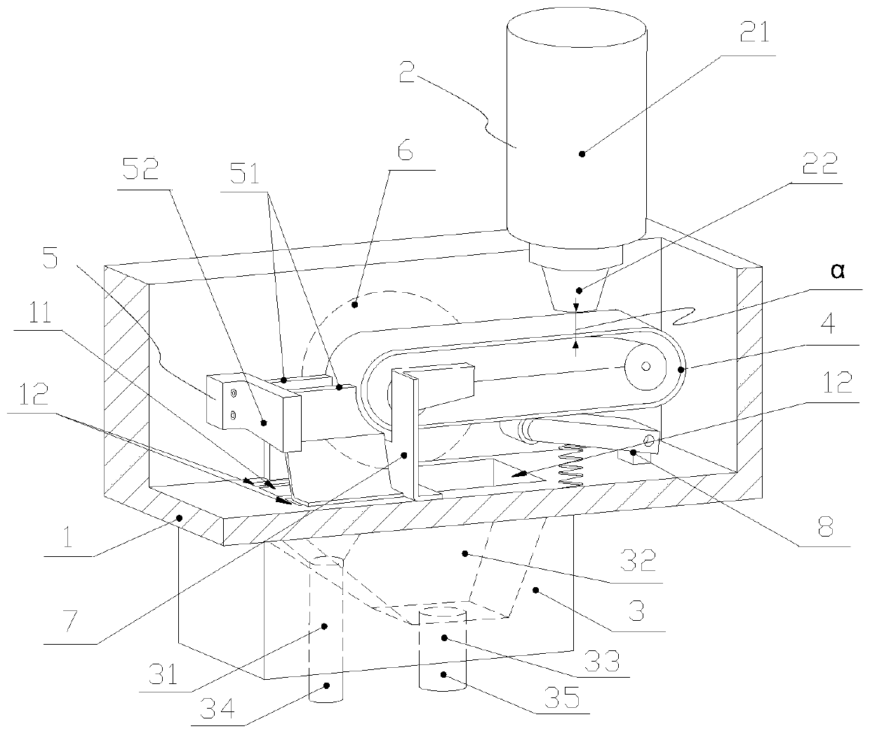
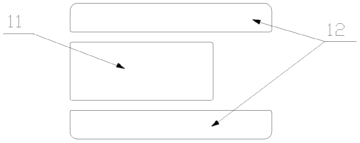
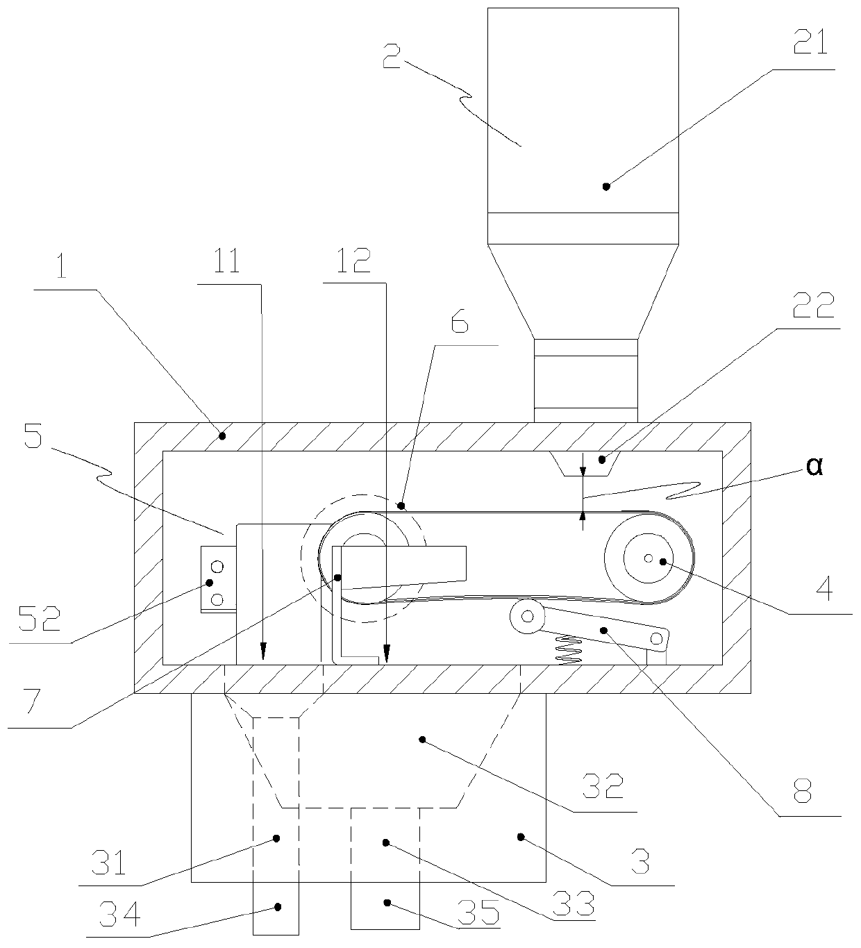
[0060] Such as figure 1 A schematic diagram of a three-dimensional structure of a large-particle solder feeder provided by an embodiment of the present invention, figure 2 A schematic cross-sectional structure diagram of a large-particle solder feeder provided by an embodiment of the present invention, image 3 A schematic diagram of the structure of a large-grain solder feeder provided in an embodiment of the present invention, Figure 4 A schematic diagram of the arrangement of the main material outlet and the auxiliary material outlet inside the shell of a large-particle solder feeder provided by the embodiment of the present invention is shown in the following figure:

[0061] A large particle solder feeder comprising:

[0062] Housing 1, material barrel 2, material chamber housing 3;

[0063] The inside of the housing 1 is provided with a conveyor belt 4 and a flow regulating mechanism 5, the bottom of the housing 1 is provided with a main material outlet 11 and an au...

Embodiment 2

[0080] This embodiment is an extended implementation of Embodiment 1, aiming at multi-level and further precise control of the flow rate of the large-particle solder.

[0081] In this implementation, the basic structure of the large-particle solder feeder is the same as that shown in Embodiment 1, except that it also includes a second flow regulating mechanism, which is arranged at the bottom or the main flow regulating mechanism 5. Below the material outlet 11.

[0082] The second flow regulating mechanism may include N flow regulating devices 5', where N is a natural number.

[0083] Figure 5 The schematic cross-sectional structure diagram of a large-particle solder feeder connected in series with the second flow regulating mechanism provided by the embodiment of the present invention shows a situation where the second flow regulating mechanism is connected in series below the flow regulating mechanism 5, and the second The scenario that the flow regulating mechanism is a...

Embodiment 3

[0093] This embodiment is based on the above-mentioned embodiment 1 or embodiment 2, and further improves the large-grain solder feeder provided by the embodiment of the present invention, so that it can achieve a better use effect.

[0094] First of all, on the basis of the above-mentioned embodiment 1 or embodiment 2, the present embodiment is provided with a switch mechanism (not shown in the figure) on the material nozzle 22, and the switch mechanism is used to open or close the material nozzle 22, so as to control the large particles Start and end of solder feeder work.

[0095] Preferably, the switch mechanism is a plate gate (not shown in the figure); the plate gate is the simplest switch mechanism, which is easy to manufacture, low in price, and not easy to be blocked.

[0096] Secondly, on the basis of the above-mentioned embodiment 1 and embodiment 2, the opening and closing mechanism (not shown in the figure) is provided at the bottom of the auxiliary material hole ...


PUM


Abstract

The invention discloses a large-particle solder feeder. A charging barrel is mounted at the upper part of a shell, the nozzle of the charging barrel extends into the shell, and a conveying belt, a flow adjusting mechanism are arranged in the shell, a main material outlet and an auxiliary material outlet are formed in the bottom, a driving device is arranged on the outer side, a material chamber shell is arranged on the outer side of the bottom of the shell, a discharging hole, an auxiliary material chamber and an auxiliary material hole are formed in the material chamber shell, the discharginghole is communicated with the main material outlet, and the auxiliary material chamber is communicated with the auxiliary material outlet and the bottom auxiliary material hole. One end of the conveying belt is arranged below the nozzle, and the other end is arranged above the main material outlet and driven by the driving device. The flow control mechanism is arranged above the main material outlet and provided with two check blocks and a fixing block fixed in the shell, the check blocks are connected to one side of the fixing block side by side to form a U-shaped structure with an opening aligned with the end of the conveying belt, the gap of the U-shaped structure is aligned with the main material outlet and the gap distance of the gap is adjustable. The speed of the conveying belt andthe flow adjusting mechanism and the flow of solder can be accurately controlled by adjusting the distance between the material nozzle and the conveying belt, and large-particle solder is not rolledor smashed.

Description

technical field [0001] The invention relates to a solder feeder, in particular to a large-grain solder feeder, and belongs to the technical field of mechanical manufacturing. Background technique [0002] Cladding surfacing is an important branch in the field of welding. It is used in the manufacture and repair of parts in metallurgy, mining, agricultural machinery, power stations, construction, petrochemical, transportation, aerospace, nuclear power and other industrial sectors, as well as the wear resistance of metal surfaces. It has a wide range of applications in corrosion surface technology. [0003] Cladding surfacing is the technology of cladding filler metal wire or powder on the surface of metal materials or parts. Specific surface properties and surface dimensions can be achieved by cladding. Cladding surfacing is mostly aimed at effectively changing the surface properties of metal parts and prolonging the service life of parts, and is widely used in the manufact...

Claims


Application Information

Patent Timeline
Patent Type & Authority Applications(China)
IPC IPC(8): B65G47/19B65G23/44B23K37/00
CPCB23K37/00B65G23/44B65G47/19
Inventor 赵克勇
Owner 上海多木实业有限公司
Why Eureka
Try Eureka