Method for obtaining dispersion characteristics and coupling impedance of slow wave structure

A technology of slow-wave structure and coupling impedance, applied in the field of linear beam microwave electric vacuum devices, can solve problems such as errors, inability to distinguish between working modes and periodic boundary conditions, and inability to effectively explain characteristics, and to avoid the limitation of periodic boundary conditions. Effect

Active Publication Date: 2020-03-24
UNIV OF ELECTRONIC SCI & TECH OF CHINA
View PDF5 Cites 0 Cited by
  • Summary
  • Abstract
  • Description
  • Claims
  • Application Information

AI Technical Summary

Problems solved by technology

The traditional calculation method for the dispersion characteristics and coupling impedance of slow-wave structures is the quasi-periodic boundary method based on the eigenmode solver. For some more complex new slow-wave structures, such as quasi-periodic slow-wave structures, over-mode slow-wave Existing theories cannot effectively explain the characteristics of slow-wave structures loaded on photonic crystals, and existing simulation calculation methods cannot be used to

Method used


Image

  • Method for obtaining dispersion characteristics and coupling impedance of slow wave structure
  • Method for obtaining dispersion characteristics and coupling impedance of slow wave structure
  • Method for obtaining dispersion characteristics and coupling impedance of slow wave structure

Examples


Embodiment

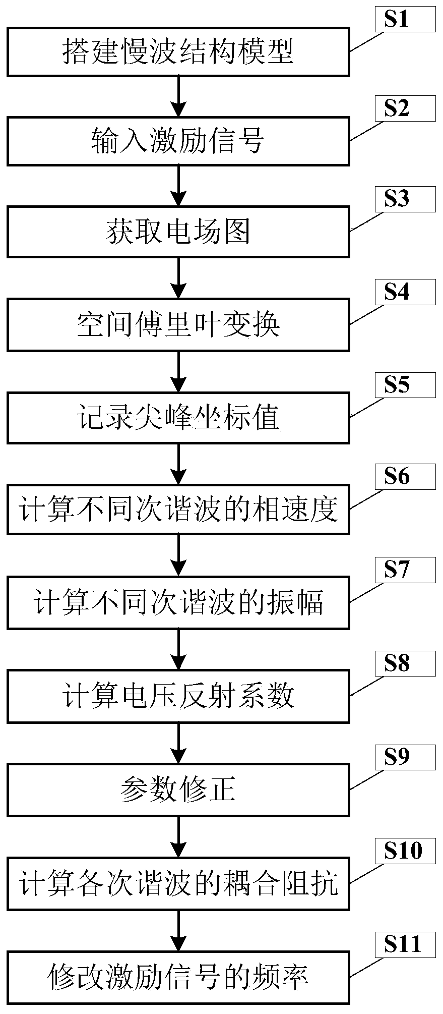
[0050] figure 1 It is a flowchart of a method for obtaining the dispersion characteristics and coupling impedance of slow wave structures in the present invention.

[0051] In this example, if figure 1 Shown, the present invention a kind of method that obtains slow-wave structure dispersion characteristics and coupling impedance, comprises the following steps:

[0052] S1. Building a slow wave structure model

[0053] S1.1. Establish a lossless slow wave structure model to be processed in the time domain solver of the electromagnetic simulation software;

[0054] In this embodiment, the electromagnetic simulation software can use CST-Microwave Studio; the slow wave structure model must be a periodic structure or a quasi-periodic structure, for example, an angle logarithmic microstrip meander slow wave structure;

[0055] S1.2. Establish a field monitoring line in the slow wave structure model, the direction of the field monitoring line is parallel to the longitudinal directio...

example

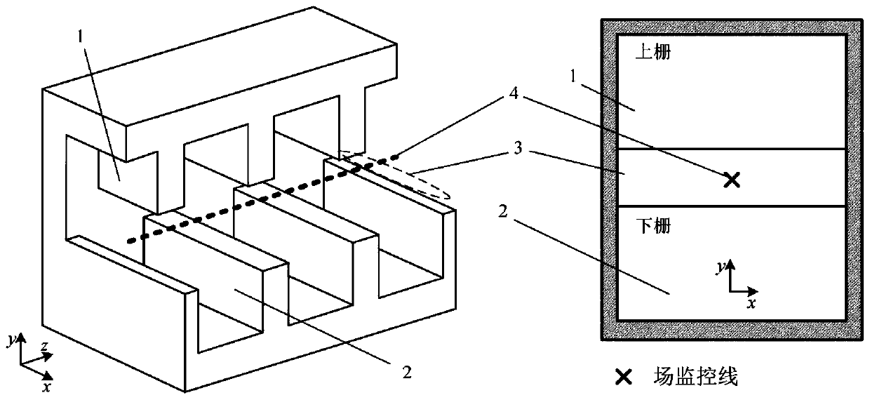
[0108] image 3 It is a schematic diagram of a common staggered double grid slow wave structure, wherein 1 is the upper grid in the staggered double grid, 2 is the lower grid, 3 is the electron injection channel, and 4 is the field monitoring line. In this embodiment, the field monitoring line It is set at the very center of the electron injection channel; the working frequency of the slow wave structure is designed to be 340GHz. First, we use the traditional quasi-periodic boundary method in HFSS to calculate the dispersion characteristics and coupling impedance of slow-wave structures. The simulation results are as follows Figure 4 shown.

[0109] Set the input signal frequency to 340GHz, simulate the interleaved double-grid slow-wave structure according to the method of the present invention, and obtain Figure 5 The longitudinal electric field distribution shown, and Image 6 The A-k diagram, wherein the left Y-axis is frequency, the right Y-axis is A (magnitude after ...


PUM


Abstract

The invention discloses a method for obtaining dispersion characteristics and coupling impedance of a slow wave structure. Firstly, a lossless slow wave structure model to be processed is established;relevant parameters of the slow wave structure model are set; sinusoidal excitation signals are input, when the energy of the slow wave structure model is stabilized at the t0 moment, a time domain field monitor extracts electric field distribution on a field monitoring line to obtain an electric field graph, then spatial Fourier transform is carried out on the electric field graph, parameter correction is carried out, and finally the dispersion characteristic and the coupling impedance of the slow wave structure are calculated.

Description

technical field [0001] The invention belongs to the technical field of line-beam microwave electric vacuum devices, and more specifically relates to a method for obtaining dispersion characteristics and coupling impedance of slow-wave structures. Background technique [0002] Microwave vacuum devices are important microwave devices, including traveling wave tubes, return wave tubes, klystrons, and gyrotrons. Among them, the traveling wave tube and the return wave tube are linear beam devices, which are important microwave power amplifiers and oscillators. The slow wave structure is their core component, and its characteristics have a crucial impact on the performance of the device. [0003] With the development of technology, in order to obtain better device performance, new slow-wave structures emerge in an endless stream. The traditional calculation method for the dispersion characteristics and coupling impedance of slow-wave structures is the quasi-periodic boundary meth...

Claims


Application Information

Patent Timeline
IPC IPC(8): G06F30/367H01J23/24
CPCH01J23/24
Inventor 许多邵伟何腾龙王禾欣王战亮宫玉彬
Owner UNIV OF ELECTRONIC SCI & TECH OF CHINA
Why Eureka
Try Eureka