
Die bonding device of die bonder and working method thereof

A die-bonding machine and die-bonding technology, which are applied in the directions of cleaning methods, chemical instruments and methods, cleaning methods and utensils using gas flow, etc. The single processing mechanism and other problems can reduce the frequency of chip installation, improve the efficiency of die bonding, and improve the smoking range.

Inactive Publication Date: 2020-03-24
马鞍山三投光电科技有限公司
View PDF6 Cites 0 Cited by
  • Summary
  • Abstract
  • Description
  • Claims
  • Application Information

AI Technical Summary

Problems solved by technology

[0004] The object of the present invention is to provide a crystal-bonding device and its working method of a crystal-bonding machine, which can solve the problem that most of the existing crystal-bonding machines are fixed structures, and only one piece can be replaced for processing at a time, and the replacement of LED chips is slow. The immobilization of the crystal-bonding mechanism affects the efficiency of LED chip bonding, and the processing mechanism for the LED chip is single, and the commonality is poor, which leads to the problem of increasing the production and processing cost of the LED chip.

Method used


Image

  • Die bonding device of die bonder and working method thereof
  • Die bonding device of die bonder and working method thereof
  • Die bonding device of die bonder and working method thereof

Examples


Embodiment Construction

[0033] The technical solutions of the present invention will be clearly and completely described below in conjunction with the embodiments. Apparently, the described embodiments are only some of the embodiments of the present invention, not all of them. Based on the embodiments of the present invention, all other embodiments obtained by persons of ordinary skill in the art without creative efforts fall within the protection scope of the present invention.

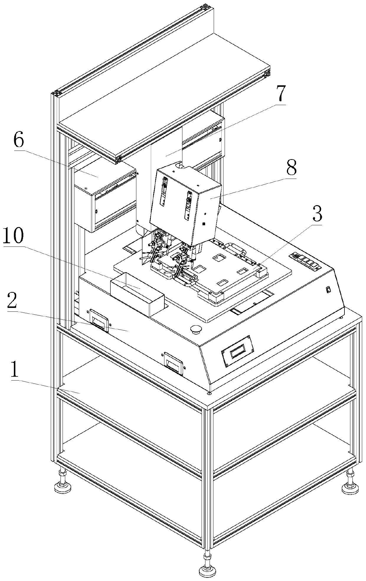
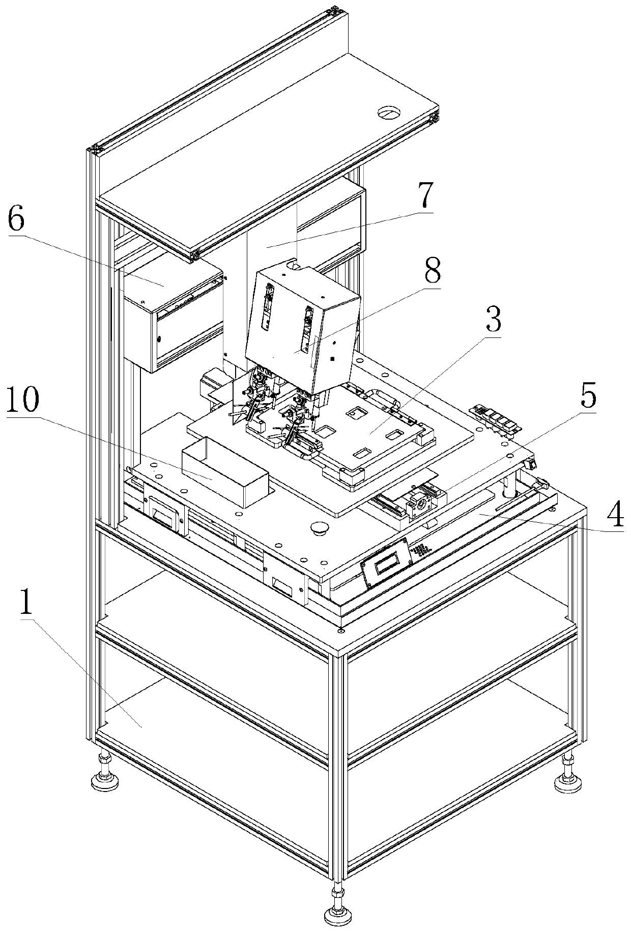
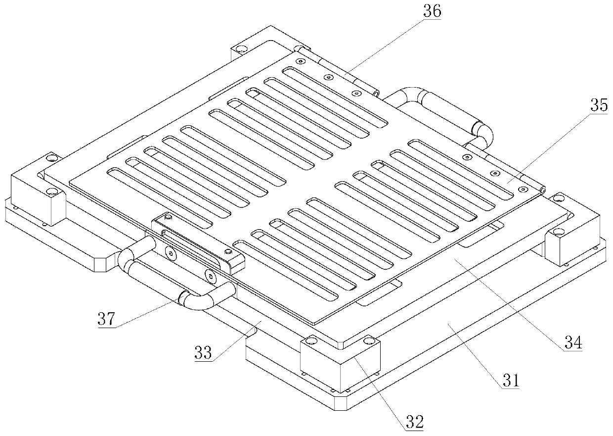
[0034]see Figure 1-8 As shown, a crystal-bonding device of a crystal-bonding machine and a working method thereof include a device frame 1, a crystal-bonding base 3, a horizontal movement mechanism 6, a vertical movement mechanism 7, and a crystal-bonding welding mechanism 8. On the device frame 1 A crystal-bonding table 101 is provided, and a crystal-bonding base 4 is fixedly installed on the crystal-bonding table 101. A crystal-bonding moving mechanism 5 is fixedly installed on the crystal-bonding base 4. The crystal-bon...


PUM


Abstract

The invention discloses a die bonding device of a die bonder and a working method thereof. The device comprises a device rack, a die bonding base, a horizontal moving mechanism, a vertical moving mechanism and a die bonding welding mechanism. A die bonding table is arranged on the device rack. A die bonding base is fixedly mounted on the die bonding table. A die bonding moving mechanism is fixedlymounted on the die bonding base. The die bonding base is connected to the die bonding moving mechanism. The die bonding base comprises a mounting bottom plate, a die bonding base plate and a hinge. Alimiting block and a supporting plate are arranged on the mounting bottom plate, the die bonding base plate is connected to the supporting plate, a positioning cover plate is rotatably connected to the die bonding base plate through the hinge, and a handle is arranged on the die bonding base plate. The replacement of the wafer is slow, the die bonding mechanism cannot move to influence the die bonding efficiency of the LED wafer, and the LED wafer processing mechanism is single and poor in universality, so that the production and processing cost of the LED wafer is improved.

Description

technical field [0001] The invention relates to the technical field of LED crystal-bonding machines, in particular to a crystal-bonding device of a crystal-bonding machine and a working method thereof. Background technique [0002] LED die bonder is a machine specialized in bonding LED products, and the most important high-speed positioning module on the die bonder is the die bonder. However, most of the existing die bonders are fixed structures, and only one can be replaced at a time. Parts are processed, and the replacement of LED chips is slow, the inability of the die-bonding mechanism to move affects the efficiency of LED chip-bonding, and the LED chip processing mechanism is single, and the commonality is poor, resulting in an increase in the cost of LED chip production and processing. [0003] The publication number is: CN204348689U patent discloses a welding head mechanism of a crystal bonder and a crystal bonder. Compared with this application, it cannot solve the p...

Claims


Application Information

Patent Timeline
Patent Type & Authority Applications(China)
IPC IPC(8): H01L21/68H01L21/687H01L33/62B08B5/04
CPCB08B5/04H01L21/68H01L21/68764H01L33/62H01L2933/0066
Inventor 张文具刘晓旭
Owner 马鞍山三投光电科技有限公司
Learn More