Deep blind hole inner wall laser cladding device

A laser cladding and deep blind hole technology, applied in metal material coating process, coating and other directions, can solve the problems of cladding processing, the inner wall of the root of the deep blind hole cannot be used, and the efficiency of laser cladding is low, so as to improve the efficiency. Effect

Pending Publication Date: 2020-03-27
XIAN BESAME LASER TECH CO LTD
View PDF2 Cites 0 Cited by
  • Summary
  • Abstract
  • Description
  • Claims
  • Application Information

AI Technical Summary

Problems solved by technology

[0004] In order to solve the technical problems that the existing laser cladding efficiency is low, and it is impossible or difficult to carry out laser cladding on the root inner wall of the deep blind hole, the invention provides a laser cladding device for the inner wall of the deep blind hole

Method used


Image

  • Deep blind hole inner wall laser cladding device

Examples


Embodiment 1

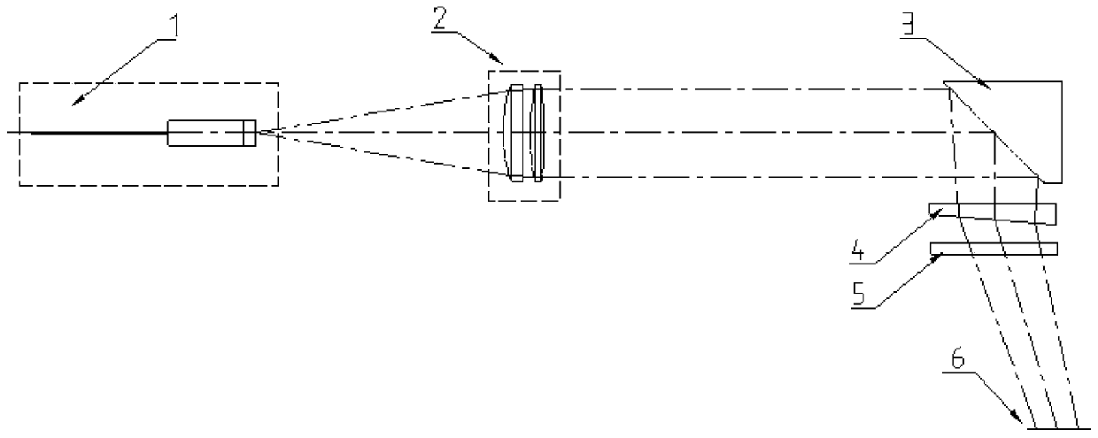
[0023] Such as figure 1 As shown, a laser cladding device for the inner wall of a deep blind hole includes a fiber laser 1 with a fiber interface and a laser beam outlet, a collimator group 2, an integrator 3, and an optical wedge arranged in sequence along the beam propagation direction of the fiber laser 1 4. Protective lens 5. The laser beam with a certain angle emitted by the laser is collimated into a parallel circular beam by the collimator lens group 2. The collimator lens group 2 can be composed of a lens or a group of lenses; The light beam is reflected by the integrating mirror 3, and the light spot at the melting pool becomes the required rectangular light spot after reflection, and after the light beam is reflected by the integrating mirror 3, the propagation direction of the light beam is deflected by 90°, and the whole light beam is deflected by a certain angle through the optical wedge 4, reaching The inner wall 6 (working surface) of the root of the processed d...

Embodiment 2

[0026] Such as figure 1 As shown, a laser cladding device for the inner wall of a deep blind hole includes a semiconductor laser with optical fiber output, a collimator lens group 2, an integrator mirror 3, an optical wedge 4, a protective lens 5, and a laser The emitted laser beam with a certain angle is collimated into a parallel circular beam by the collimator lens group 2, which can be composed of a lens or a group of lenses; the parallel circular beam is reflected by the integrator mirror 3, After reflection, the light spot at the molten pool becomes the required rectangular light spot, and after the integrator mirror 3 reflects the beam propagation direction and deflects 90°, the light beam is deflected by a certain angle through the optical wedge 4 to reach the processed deep blind hole. The inner wall 6 (working surface) of the root, so that the inner wall of the deep blind hole is completely clad, and the protective lens 5 is located below the optical wedge 4 (in the ...


PUM


Abstract

The invention belongs to the laser cladding technology, and provides a deep blind hole inner wall laser cladding device. The problems that existing laser cladding efficiency is low, and laser claddingmachining cannot be conducted on the inner wall of the root of a deep blind hole or is difficult are solved. The device comprises an optical fiber laser, a collimating mirror set, an integral mirror,an optical wedge and a protective lens, wherein the optical fiber laser is used for outputting a laser beam with a divergence angle; the collimating mirror set is positioned in an emergent light pathof the optical fiber laser and used for collimating the laser beam with the divergence angle output by the optical fiber laser into parallel circular light beams and transmitting the parallel circular light beams to the integral mirror; the integral mirror is used for reflecting the parallel circular light beams, and light spots of the reflected light beams at a molten pool are rectangular lightspots; the optical wedge is positioned in an emergent light path of the integral mirror and used for deflecting the light beams to the inner wall of the root of the machined deep blind hole; and the protective lens is positioned in an emergent light path of the optical wedge.

Description

technical field [0001] The invention belongs to the laser cladding technology, in particular to a laser cladding device for the inner wall of a deep blind hole. Background technique [0002] Laser cladding technology is an advanced manufacturing technology combining laser technology and processing technology, which has developed rapidly in recent years. As an advanced surface modification technology, it is widely used in the surface modification of materials and the repair of failed parts, which solves many problems in engineering practice and creates huge economic benefits in engineering practice. [0003] In common laser processing production, the laser cladding of small-diameter inner holes and deep holes is limited by space, which hinders the wide application of laser cladding processing. For example, the publication number CN 204825050 U, the patent name is a laser cladding head for inner holes, and the publication number CN206337314U, the patent name is a deep hole la...

Claims


Application Information

Patent Timeline
Patent Type & Authority Applications(China)
IPC IPC(8): C23C24/10
CPCC23C24/10
Inventor 王晓飚汤波
Owner XIAN BESAME LASER TECH CO LTD
Why Eureka
Try Eureka