Step-shaped magnetorheological damper

A magnetorheological shock absorber, step-shaped technology, applied in the field of magnetorheology, can solve the problem of small damping force, achieve the effect of increasing damping force, overcoming insufficient damping force, and improving damping force and damping effect

A magnetorheological shock absorber, step-shaped technology, applied in the field of magnetorheology, can solve the problem of small damping force, achieve the effect of increasing damping force, overcoming insufficient damping force, and improving damping force and damping effect

CN110925351APending Publication Date: 2020-03-27GUANGXI UNIVERSITY OF TECHNOLOGY

Image

  • Step-shaped magnetorheological damper

Examples


Embodiment Construction

[0028] The present invention will be further described below in conjunction with accompanying drawing.

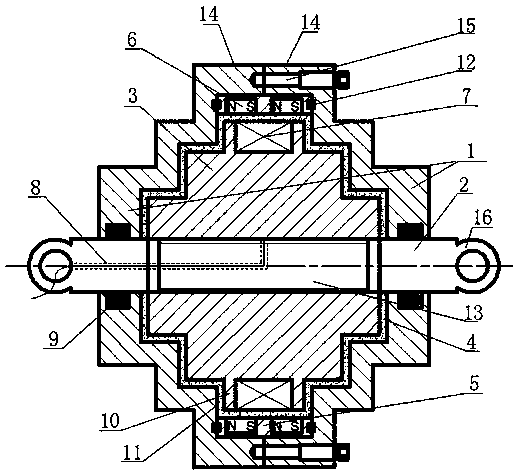
[0029] Such as figure 1 As shown, the stepped magnetorheological shock absorber includes a working cylinder 1, a piston rod 2, a piston body 3, a magnetorheological fluid 4, a permanent magnet positioning ring 5, a permanent magnet ring 6, and a coil 7;

[0030] The piston body 3 is in the shape of a stepped shaft, and the middle one is a primary shaft 10 with the largest radius. There are more than one set of secondary shafts arranged on the left and right sides of the primary shaft 10, with the primary shaft 10 facing the left and right sides, The radius of each secondary axis decreases in turn;

[0031] The left and right end walls of the working cylinder 1 are respectively provided with piston rod holes, and the two ends of the piston rod 2 pass through the left and right end surfaces of the working cylinder 1 respectively through the piston holes, and can be moved alo...


PUM


Abstract

The invention aims to provide a step-shaped magnetorheological damper. The step-shaped magnetorheological damper comprises a working cylinder, a piston rod, a piston body of an electromagnetic piston,magnetorheological fluid, a permanent magnet positioning ring, a permanent magnet ring and a coil, wherein the piston body is in a step shaft shape. The step-shaped magnetorheological damper can solve the problems of small damping force and the like in the prior art, meanwhile, the volume of the magnetorheological fluid for working is reduced, the magnetorheological damping force is greatly improved, and the step-shaped magnetorheological damper has the advantages that the required magnetorheological fluid dosage is small, and the magnetorheological effect is remarkable.

Description

technical field [0001] The invention belongs to the field of magnetorheological technology, and in particular relates to a stepped magnetorheological shock absorber. Background technique [0002] The magnetorheological shock absorber is a new type of shock absorber that uses the controllable fluid of magnetorheological fluid. Under different magnetic fields, the shear yield strength of the magnetorheological fluid is different, and the shear force that forces the magnetorheological fluid to flow is also different, that is to say, the damping force provided by the magnetorheological shock absorber is variable. Therefore, by controlling the external magnetic field, the purpose of adjusting the damping force of the magneto-rheological shock absorber can be achieved. It is precisely because the magneto-rheological damper has this important engineering application value that it has caused extensive research on the magnetorheological damper in the industry. [0003] According to...

Claims


Application Information

Patent Timeline
27 Mar 2020
Publication
CN110925351A
IPC
F16F9/53
CPC
F16F9/535
Inventors
杨小龙; 王梓骄