Flow battery capable of realizing sealing and battery stack

A liquid flow battery and side sealing technology, which is applied to fuel cells, regenerative fuel cells, circuits, etc., can solve the problems of complex sealing structure assembly, high manufacturing difficulty, and poor sealing effect of liquid flow batteries. The method is simple, novel, and sealed Good effect, convenient and quick adjustment effect

Active Publication Date: 2020-04-07
CHNA ENERGY INVESTMENT CORP LTD +1
View PDF13 Cites 3 Cited by
  • Summary
  • Abstract
  • Description
  • Claims
  • Application Information

AI Technical Summary

Problems solved by technology

[0008] The purpose of the present invention is to provide a liquid flow battery and a battery stack that can achieve sealing in order to overcome the problems of poor sealing effect of the liquid flow battery, complex assembly of the sealing structure, and great difficulty in manufacturing in the prior art

Method used


Image

  • Flow battery capable of realizing sealing and battery stack
  • Flow battery capable of realizing sealing and battery stack
  • Flow battery capable of realizing sealing and battery stack

Examples


Embodiment approach

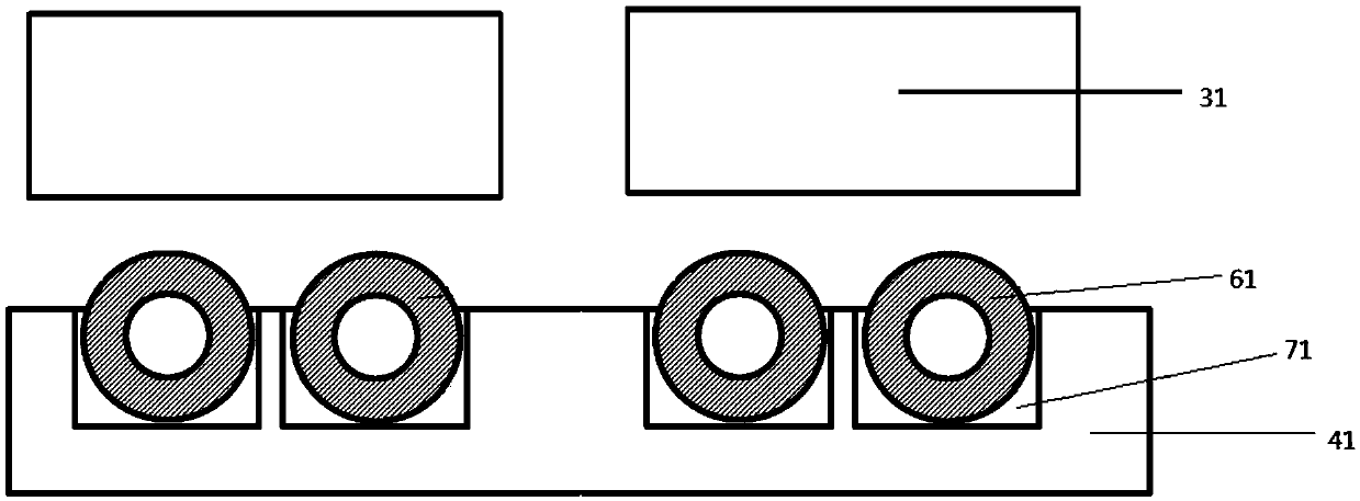
[0061] According to a preferred embodiment of the present invention, the cross-sectional diameter of the sealing ring 61 is larger than the width of the groove 71 ; the cross-sectional diameter of the opposite side sealing ring 62 is larger than the width of the groove 71 .

[0062] Further preferably, the cross-sectional diameter of the sealing ring 61 is 0.1-0.5 mm larger than the width of the groove 71 , preferably 0.2-0.4 mm. Further preferably, the cross-sectional diameter of the opposite side sealing ring 62 is 0.1-0.5 mm larger than the width of the opposite side groove 72 , preferably 0.2-0.4 mm. Adopting this preferred embodiment is more conducive to achieving better sealing, avoiding micro-leakage, and more conducive to improving the local gap-filling function of the flow battery.

[0063] The cross-sectional diameter mentioned in the present invention refers to the outer diameter of the ring when the cross-section of the sealing ring 61 and the opposite side sealing...

Embodiment 1

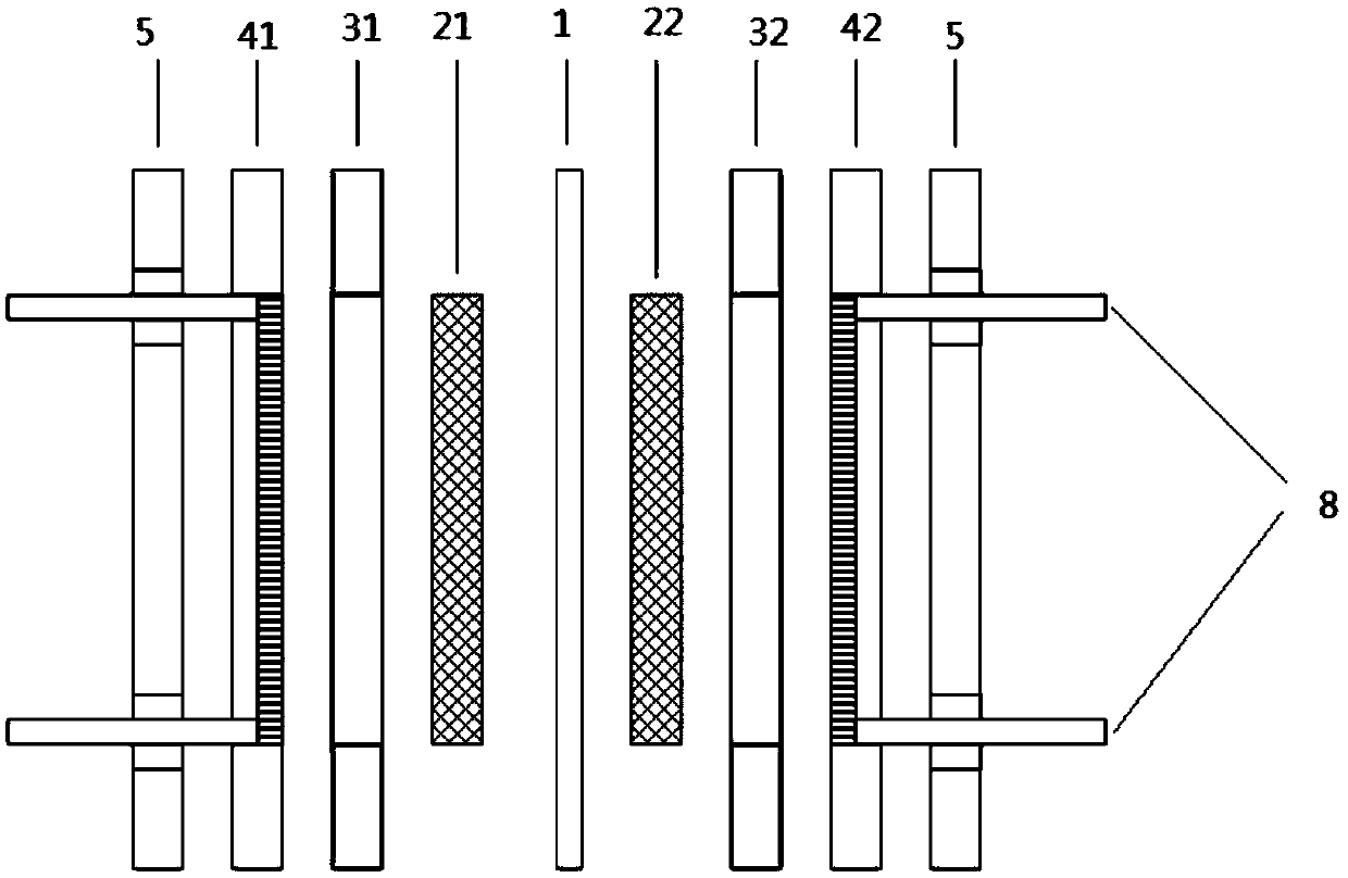
[0092] Flow battery such as figure 1 As shown, it includes: a diaphragm 1; one side of the diaphragm 1 is sequentially provided with an electrode 21 (porous carbon fiber felt, commercially available from SGL, the brand is KFD2.5EA, and the size is 200mm×200mm×2.5mm), a sealing gasket 31 and double Pole plate 41 (300mm×300mm×3mm, made of graphite); the opposite side electrode 22 (same as electrode 21), opposite side gasket 32 ​​and opposite side bipolar plate 42 (same as bipolar plate) are arranged in sequence on the other side of diaphragm 1 41). Such as Figure 5 As shown, the flow battery also includes an electrolyte storage tank 81, an electrolyte inlet 91, an electrolyte outlet 101, an opposite electrolyte storage tank 82, an opposite electrolyte inlet 92, and an opposite electrolyte outlet 102; the electrolyte inlet 91 and the electrolyte outlet 101 make the electrolyte in the electrolyte storage tank 81 circulate between the electrolyte storage tank 81 and the electrod...

Embodiment 2

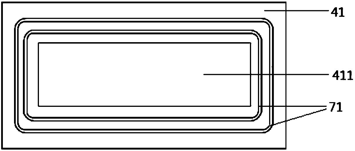
[0101] Assembling the flow battery according to Example 1, the difference is that a circle of grooves is provided on the bipolar plate 41 and the opposite bipolar plate 42, the grooves of the outer ring are reserved, and the grooves of the inner ring are not provided. The sealing ring of the inner ring is not provided, the width of the sealing gasket is 10mm, and the schematic diagram of the bipolar plate 42 on the opposite side is as follows Figure 6 , Figure 7 shown.


PUM

PropertyMeasurementUnit
thicknessaaaaaaaaaa
widthaaaaaaaaaa

Abstract

The invention relates to the field of flow batteries, and discloses a flow battery capable of realizing sealing and a battery stack. The flow battery comprises: a diaphragm; an electrode, a sealing gasket and a bipolar plate sequentially arranged on one side of the diaphragm; sealing rings; a current collecting area and grooves matched with the sealing rings arranged on the bipolar plate, whereinthe grooves are arranged at the outer portion of the current collecting area in a surrounding mode, the sealing rings are arranged in the grooves, and the sealing gasket covers the sealing rings; an opposite-side electrode, an opposite-side sealing gasket and an opposite-side bipolar plate arranged at the other side of the diaphragm; opposite-side sealing rings; an opposite-side flow collecting area and opposite-side grooves matched with the opposite-side sealing rings arranged at the opposite side bipolar plate, wherein the opposite-side grooves are arranged at the outer portion of the opposite-side flow collecting area in a surrounding mode, the opposite-side sealing rings are arranged in the opposite-side grooves, and the opposite-side sealing gasket covers the opposite-side sealing rings; and fastening parts used for pressing the flow battery, so that the sealing rings and the opposite-side sealing rings deform to realize sealing. The flow battery provided by the invention can realize better sealing, and is simple to assemble and low in manufacturing difficulty.

Description

technical field [0001] The invention relates to the field of liquid flow batteries, in particular to a liquid flow battery and a battery stack capable of being sealed. Background technique [0002] Energy storage technology is a key technology that restricts social development in many fields. In the field of transportation, electric vehicles are considered to be widely used as substitutes for internal combustion locomotives due to their advantages such as zero emissions and environmental protection. However, due to disadvantages such as poor battery life and poor safety, their large-scale promotion is still difficult. In the field of electric power, thermal power generators need energy storage technology for frequency regulation, and new energy technologies such as photovoltaic and wind energy need energy storage technology to smooth the output, so as to achieve large-scale grid connection. In the field of information and communication, a large number of signal base station...

Claims


Application Information

Patent Timeline
Patent Type & Authority Applications(China)
IPC IPC(8): H01M8/18H01M8/0271H01M8/0273H01M8/2465
CPCH01M8/0271H01M8/0273H01M8/188H01M8/2465Y02E60/50
Inventor 刘庆华孙永伟龙银花康利斌梁朋潘广宏马浩初李永龙
Owner CHNA ENERGY INVESTMENT CORP LTD
Why Eureka
Try Eureka