Flow cell stack

A technology of liquid flow batteries and electric stacks, applied in fuel cells, regenerative fuel cells, circuits, etc., can solve the problems of weakening local thermal effects, increasing electrolyte utilization, and uneven flow velocity distribution, so as to reduce local heat release and improve Battery performance, the effect of suppressing local overheating

Pending Publication Date: 2020-04-07
DALIAN INST OF CHEM PHYSICS CHINESE ACAD OF SCI +1
View PDF0 Cites 1 Cited by
  • Summary
  • Abstract
  • Description
  • Claims
  • Application Information

AI Technical Summary

Problems solved by technology

[0005] Aiming at the uneven flow velocity distribution of the electrolyte in the direction perpendicular to the flow direction in the flow battery, especially in the flow battery stack, a structure suitable for the flow battery stack is proposed and studied, which has a simple structure and is easy to process. By adding a cavity for buffering and redistribution of the electrolyte near the inlet and outlet of the electrode area, the electrolyte can be evenly flowed into and out of the electrode reaction area, so as to achieve uniform distribution of the electrolyte, weaken the local thermal effect, and improve the efficiency of the electrolyte reaction. Uniformity, reduce concentration polarization, increase electrolyte utilization

Method used


Image

  • Flow cell stack
  • Flow cell stack
  • Flow cell stack

Examples


Embodiment 1

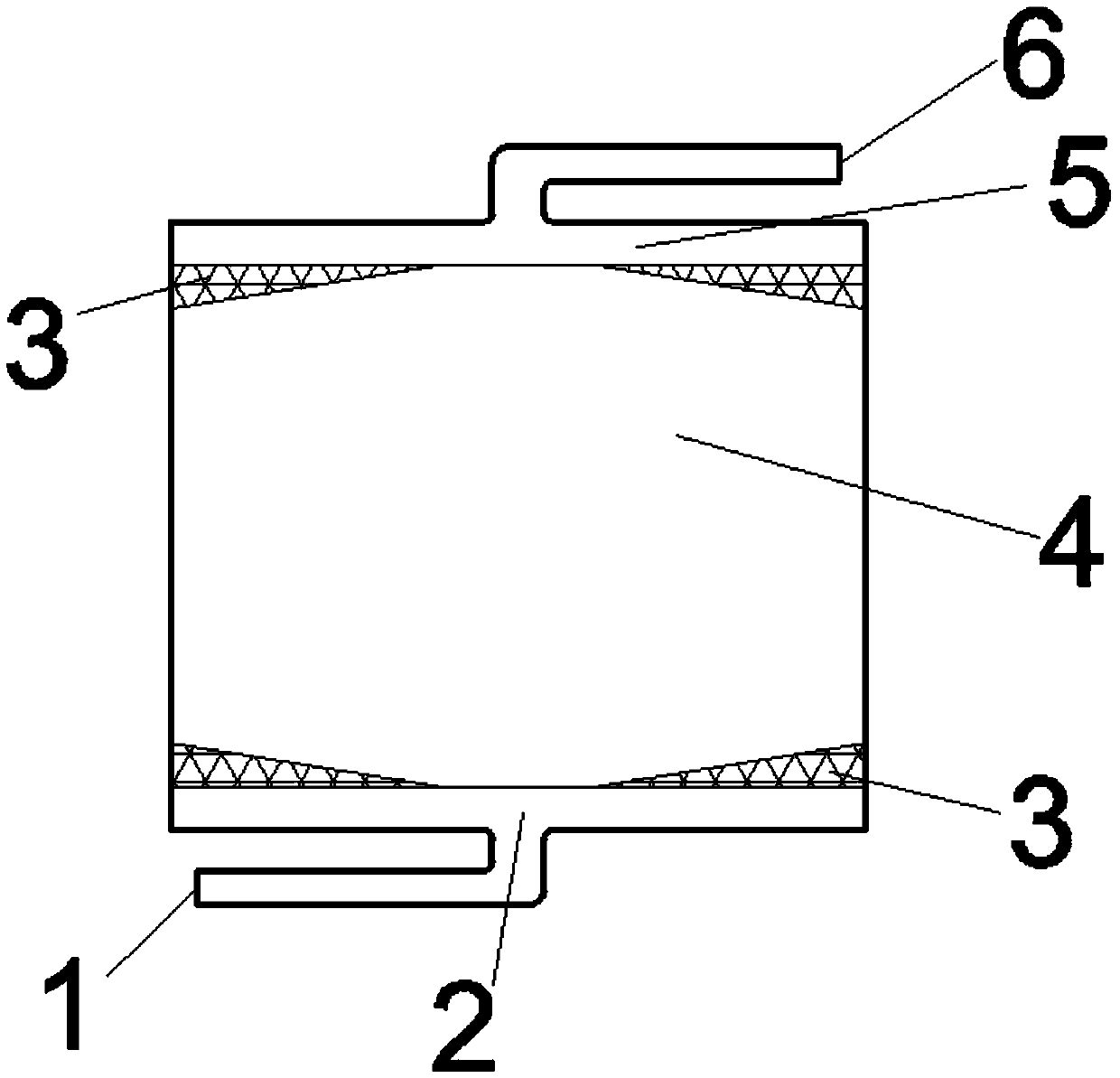
[0020] Such as figure 1 As shown, a flow battery assembly structure. The outside of the area shown in the figure is the liquid flow frame, and the figure is the main area through which the electrolyte flows, including the inlet diversion area 2 , the buffer cavity 3 , the porous electrode 4 and the outlet diversion area 5 . The main electrolyte inlet 1 is arranged on the inlet guide area, the main electrolyte outlet 6 is arranged on the outlet guide area, and the buffer cavity is located between the porous electrode 4 and the liquid flow frame. The porous electrode is an octagon with a maximum width of 30mm in the horizontal direction and a maximum width of 25mm in the vertical direction. The length of the top and bottom sides is 8mm, and the width of the sides attached to the electrode frame on the left and right sides is 17mm. Felt; four cavities are arranged around the porous electrode, which are triangular in shape. The horizontal width of the inlet guide area and the ou...

Embodiment 2

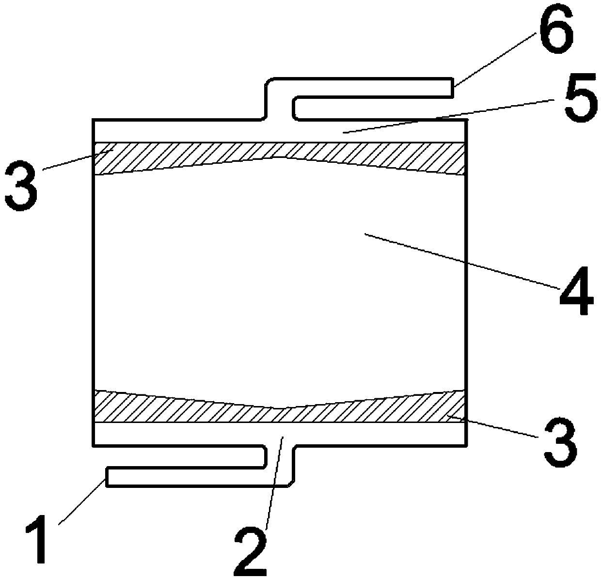
[0022] Such as figure 2 As shown, a flow battery assembly structure. The outside of the area shown in the figure is the liquid flow frame, and the figure is the main area through which the electrolyte flows, including the inlet diversion area 2 , the buffer cavity 3 , the porous electrode 4 and the outlet diversion area 5 . The main electrolyte inlet 1 is arranged on the inlet guide area, the main electrolyte outlet 6 is arranged on the outlet guide area, and the buffer cavity is located between the porous electrode 4 and the liquid flow frame. The porous electrode is a hexagon with a maximum width of 30mm in the horizontal direction and a maximum width of 17mm in the vertical direction. A cavity is provided, which is in the shape of a concave pentagon, with a maximum vertical width of 5mm and a minimum width of 4mm. The horizontal width of the inlet guide area and the outlet guide area is equal to the width of the porous electrode, which is 30 mm.

Embodiment 3

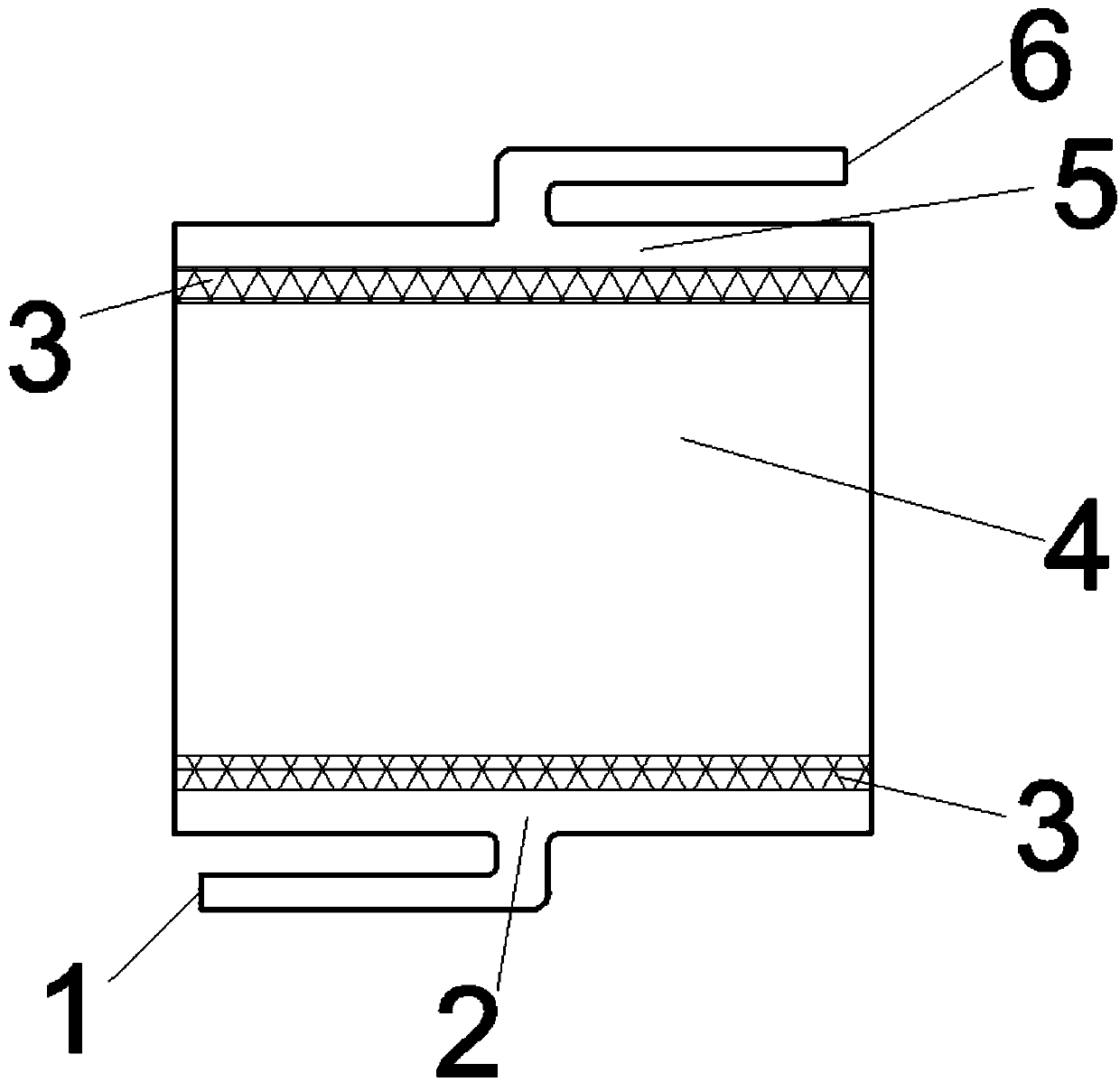
[0024] Such as image 3 As shown, a flow battery assembly structure. The outside of the area shown in the figure is the liquid flow frame, and the figure is the main area through which the electrolyte flows, including the inlet diversion area 2 , the buffer cavity 3 , the porous electrode 4 and the outlet diversion area 5 . The main electrolyte inlet 1 is arranged on the inlet guide area, the main electrolyte outlet 6 is arranged on the outlet guide area, and the buffer cavity is located between the porous electrode 4 and the liquid flow frame. The porous electrode is a rectangle with a length of 30 mm in the horizontal direction and a width of 20 mm in the vertical direction, made of carbon felt; the inlet and outlet sides of the porous electrode are each provided with a cavity, which is rectangular in shape, 30 mm long in the horizontal direction and 5 mm wide in the vertical direction. The horizontal width of the inlet guide area and the outlet guide area is equal to the w...


PUM

PropertyMeasurementUnit
widthaaaaaaaaaa

Abstract

The invention relates to the field of flow cells, particularly relates to a flow cell stack assembly structure. The flow cell stack assembly structure comprises a sheet porous electrode and a liquid flow frame provided with a through hole with the shape and the size corresponding to those of the liquid flow frame; the porous electrode is arranged in the middle through hole of the liquid flow frame; the peripheral edges of the porous electrode are attached to the inner wall surface of the middle through hole of the liquid flow frame; a through hole serving as an electrolyte inflow channel and athrough hole serving as an electrolyte outflow channel are formed in the liquid flow frame; the through hole of the electrolyte inflow channel communicates with the middle through hole through a groove or a through hole serving as an inlet flow guide area, and the through hole of the electrolyte outflow channel communicates with the middle through hole through a groove or a through hole serving as an outlet flow guide area. The flow cell stack assembly structure is characterized in that a cavity for buffering and redistributing the electrolyte is formed near the inner wall surface of the liquid flow frame at the middle through hole where the inlet flow guide area and the outlet flow guide area are located; and the inlet or outlet flow guide area communicates with the middle through hole through the cavity.

Description

technical field [0001] The invention relates to the field of liquid flow batteries, in particular to an assembly structure of a liquid flow battery cell stack. Background technique [0002] Energy storage technology is an effective strategy to deal with problems such as the effective use of renewable energy and environmental pollution. Among many energy storage technologies, flow battery technology is a new electrochemical energy storage technology because it usually has energy storage capacity and power independence. It has attracted wide attention due to its design and other advantages. Electric propulsion is the core component of the flow battery, and its performance is directly related to the performance and cost of the entire system. The stack includes end plates, electrodes, liquid flow frames, ion exchange membranes and other components During the operation of the flow battery, the active substances dissolved in the electrolyte circulate and flow between the liquid s...

Claims


Application Information

Patent Timeline
Patent Type & Authority Applications(China)
IPC IPC(8): H01M8/2455H01M8/2465H01M8/18
CPCH01M8/188H01M8/2455H01M8/2465Y02E60/50
Inventor 郑琼岳孟张华民李先锋
Owner DALIAN INST OF CHEM PHYSICS CHINESE ACAD OF SCI
Why Eureka
Try Eureka