

High temperature resistant adjustable frequency flexible antenna and manufacturing method thereof
A technology for flexible antennas and manufacturing methods, applied to antennas, devices that allow antennas to work in different bands at the same time, electrical components, etc., can solve problems such as single working environment, inability to adapt to multi-scenario applications, single operating frequency of flexible antennas, etc. , to achieve the effect of high elasticity, good flexibility and excellent insulation performance
- Summary
- Abstract
- Description
- Claims
- Application Information
AI Technical Summary
Problems solved by technology
Method used
Image

Examples
Embodiment 1
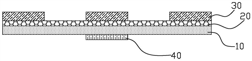
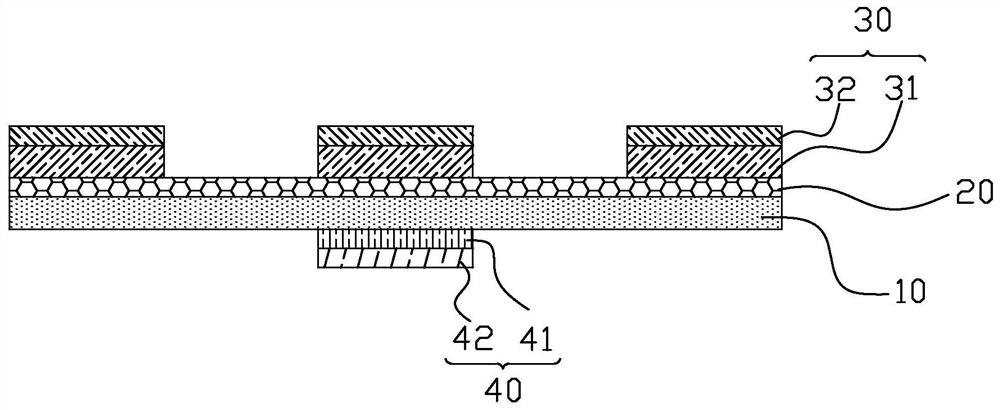
[0068] A flexible mica sheet 10 with a thickness of 10 μm was placed in a vacuum chamber and evacuated to 3×10 -3 Pa. Fill the vacuum chamber with Ar to make the vacuum degree 0.1Pa, turn on the heater power, heat the flexible mica sheet 10 to 50°C, turn on the Plasma power supply, adjust the voltage to 1000V, and the flexible mica sheet 10 is heated by the generated Ar plasma. Process 2min. Power off Plasma and evacuate to 3×10 -3 Pa, heat the flexible mica sheet 10 to 300°C, and fill the vacuum chamber with Ar and O at the same time 2 , the ratio of their flow values is 2:1, so that the vacuum degree is 0.1Pa, turn on the magnetron sputtering power supply, adjust the power to 80W, and form a dielectric adjustable barium titanate material for the flexible mica sheet 10 magnetron sputtering deposition. For the ceramic thin film 20, the deposition time is 10 minutes, and the thickness of the dielectric tunable ceramic thin film 20 is 200 nm. Incubate in oxygen for 20 min,...
Embodiment 2
[0070] A flexible mica sheet 10 with a thickness of 50 μm was placed in a vacuum chamber and evacuated to 3×10 -3 Pa. Fill the vacuum chamber with O 2 , the vacuum degree is 0.5Pa, the heater power is turned on, the flexible mica sheet 10 is heated to 150°C, the Plasma power is turned on, the voltage is adjusted to 2000V, and the flexible mica sheet 10 is treated by the generated oxygen plasma for 20min. Power off Plasma and evacuate to 3×10 -3 Pa, heating the flexible mica sheet 10 to 700°C, and filling the vacuum chamber with Ar and O at the same time 2 , the ratio of their flow values is 5:1, so that the vacuum degree is 0.5Pa, turn on the magnetron sputtering power supply, adjust the power to 150W, and deposit 10 magnetron sputtering on the flexible mica sheet. The ceramic thin film 20 is adjusted, the deposition time is 2h, and the thickness is 2.4 μm. Incubate in oxygen for 60 min, and cool to room temperature. The screen printing screen with a mesh size of 300 me...
Embodiment 3
[0072] The flexible mica sheet 10 with a thickness of 10 μm is sandblasted to make the surface roughness 100 nm, and placed in a vacuum chamber, evacuated to 3×10 -3 Pa. Fill the vacuum chamber with Ar to make the vacuum degree 0.1Pa, turn on the heater power, heat the flexible mica sheet 10 to 50°C, turn on the Plasma power supply, adjust the voltage to 1000V, and the flexible mica sheet 10 is heated by the generated Ar plasma. Process 2min. Turn off the Plasma power and evacuate to 3×10 -3 Pa, heat the flexible mica sheet 10 to 300°C, and fill the vacuum chamber with Ar and O at the same time 2 , the ratio of their flow values is 2:1, so that the vacuum degree is 0.1Pa, turn on the magnetron sputtering power supply, adjust the power to 80W, and deposit the barium titanate material on the mica sheet by magnetron sputtering to form a dielectric tunable ceramic film 20, the deposition time is 10 min, and the thickness is 200 nm. Incubate in oxygen for 20 min, then cool to...
PUM
| Property | Measurement | Unit |
|---|---|---|
| thickness | aaaaa | aaaaa |
| thickness | aaaaa | aaaaa |
| thickness | aaaaa | aaaaa |
Abstract
Description
Claims
Application Information