Fluorescence imaging system for experimental animals

A fluorescence imaging and experimental animal technology, applied in the field of biomedicine, can solve the problems of affecting the activities of experimental animals, single function, large size, etc., and achieve the effect of easy expansion, good imaging effect, and small size

Pending Publication Date: 2020-04-10
北京脑科学与类脑研究中心
View PDF11 Cites 6 Cited by
  • Summary
  • Abstract
  • Description
  • Claims
  • Application Information

AI Technical Summary

Problems solved by technology

[0005] Aiming at the above defects or improvement needs of the prior art, the present invention provides a wearable multi-light source fluorescence imaging system for experimental animals, the purpose of which is to externalize the light source of the imaging system and Simplify the illumination light path, thereby reducing the weight of the wearable system and expanding the luminous ability of the light source, thereby solving the technical problems of the existing wearable fluorescence imaging system with single function or large volume and heavy weight affecting the activities of experimental animals

Method used


Image

  • Fluorescence imaging system for experimental animals
  • Fluorescence imaging system for experimental animals
  • Fluorescence imaging system for experimental animals

Examples


Embodiment 1

[0043] Example 1 In situ optogenetics-monochromatic fluorescence imaging

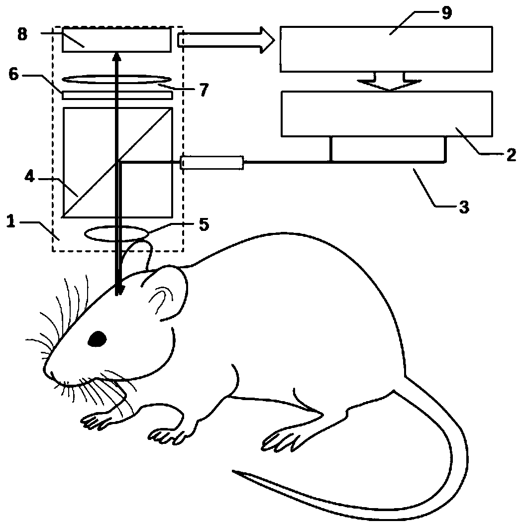
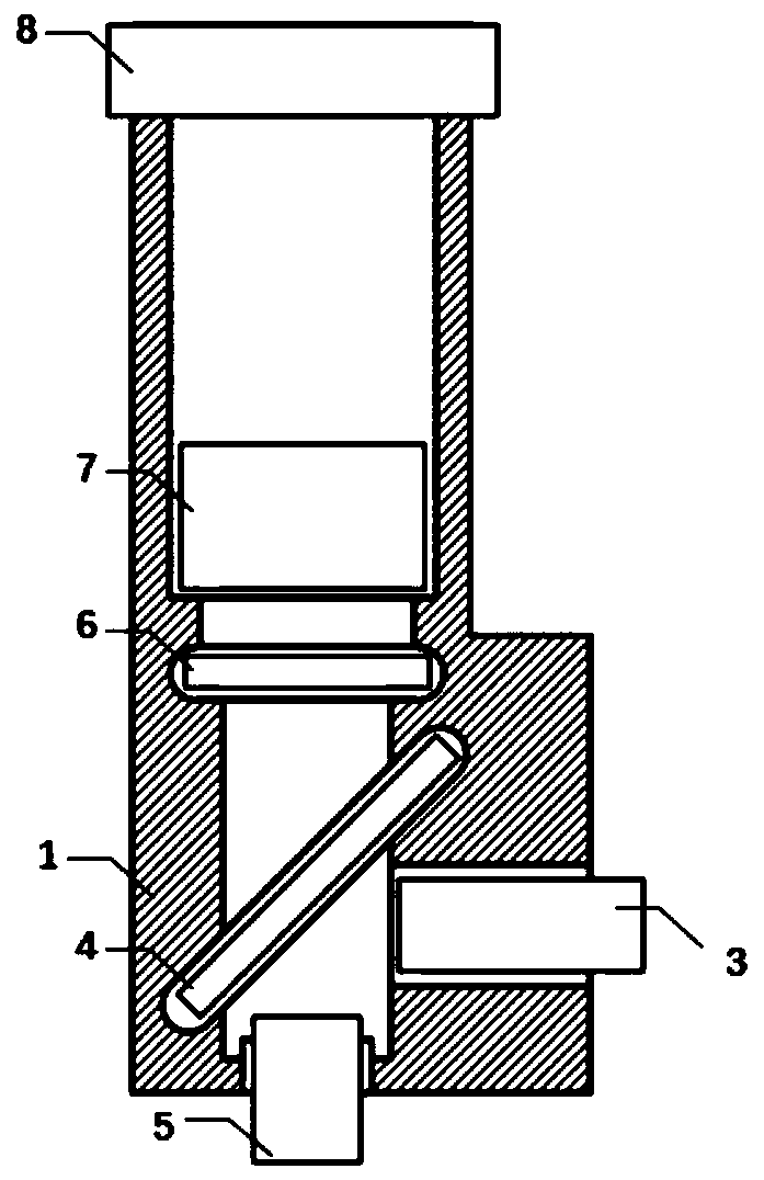
[0044] A wearable multi-light source fluorescence imaging system for experimental animals, such as figure 1 , figure 2 As shown, including: mirror body, light source light path and fluorescence imaging light path;

[0045] The optical path of the light source is used to project the light source on the target fluorescently marked tissue; it includes a plurality of light-emitting units, a coupling optical fiber bundle, a dichroic mirror and an objective lens for respectively generating fluorescence excitation light or stimulation light of different wavelengths;

[0046] The light emitting unit includes a light source and its driving module. The light source is the first and second external lasers, both of which have standard FC interfaces. The laser generates stimulating laser light of 633nm, and the output power can reach 100mw. The driving module is used to modulate the second laser according to the ...

Embodiment 2

[0055] Embodiment 2 two-color fluorescence imaging system

[0056] A wearable multi-light source fluorescence imaging system for experimental animals, such as figure 1 , figure 2 As shown, including: mirror body, light source light path and fluorescence imaging light path;

[0057] The optical path of the light source is used to project the light source on the target fluorescently marked tissue; it includes two light-emitting units for respectively generating two wavelengths of fluorescent excitation light, a coupling fiber bundle, a dichroic mirror and an objective lens;

[0058] The light emitting unit includes a light source and its driving module, the light source is a combination of ~470nm high-power LED-narrow-band filter and a combination of ~560nm LED high-power LED-narrow-band filter, and the driving module is used to Modulate the light source. Cooperating with the imaging frame rate of the imaging unit, the two light sources are turned on time-sharingly.

[0059...

Embodiment 3

[0066] Example 3 In situ optogenetics-two-color fluorescence imaging

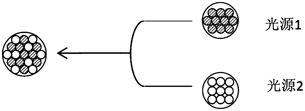
[0067] A wearable multi-light source fluorescence imaging system for experimental animals, such as figure 2 , Figure 5 As shown, including: mirror body, light source light path and fluorescence imaging light path;

[0068] The optical path of the light source is used to project the light source on the target fluorescently marked tissue; it includes a plurality of light-emitting units, a coupling optical fiber bundle, a dichroic mirror and an objective lens for respectively generating fluorescence excitation light or stimulation light of different wavelengths;

[0069] The light-emitting unit includes a light source and its drive module, the light source is a combination of ~470nm high-power LED-narrow-band filter, a combination of ~560nm high-power LED-narrow-band filter, and a 633nm external laser. It is used to modulate the light source according to the external TTL signal. ~470nm LED light source an...


PUM

PropertyMeasurementUnit
diameteraaaaaaaaaa
diameteraaaaaaaaaa
diameteraaaaaaaaaa

Abstract

The invention discloses a fluorescence imaging system for experimental animals. The system comprises a light source light path and a fluorescence imaging light path; the light source light path and the fluorescence imaging light path share a dichroscope and an objective lens; the light source light path also comprises a coupling optical fiber bundle and a plurality of light emitting units used forrespectively generating fluorescence excitation light or light genetic stimulation light with different wavelengths; the coupling optical fiber bundle comprises a plurality of optical fibers, whereinthe light emitting ends of the coupling optical fiber bundles are tightly arranged, and the light entering ends of the coupling optical fiber bundles are divided into a plurality of sub-bundles; thelight entering ends of the plurality of sub-bundles are respectively matched and coupled with the plurality of light emitting units; a plurality of optical fibers of each bundle of the plurality of sub-bundles are uniformly distributed at the light emitting ends; the optical fibers of the plurality of sub-bundles are mixed and arranged in the coupling optical fiber bundle; and the distance from the light emitting ends of the optical fibers to the rear end face of the objective lens is within 2.5 times of the focal length; and the fluorescence imaging optical path also comprises an imaging unitand an image acquisition unit. The fluorescence imaging system has the advantages of small volume, light weight, good imaging effect and easy expansion, and can realize multi-color fluorescence imaging and in-situ light genetic fluorescence imaging.

Description

technical field [0001] The invention belongs to the field of biomedicine, and more specifically relates to a wearable multi-light source fluorescence imaging system for experimental animals. Background technique [0002] The detection of neuronal activity signals is the basis of neuroscience research. Conventional methods such as electrophysiological recording have many problems such as technical difficulty, low throughput, non-specificity, and lack of spatial resolution. The development of optical neural probes such as calcium-sensitive fluorescent probes, neurotransmitter-sensitive probes, and voltage-sensitive probes has made it possible to apply optical imaging technology to the detection and recording of neural activity, and it has made up for the shortcomings of traditional technologies. , is an important supplement to the detection technology of modern neuroscience research. [0003] Widefield fluorescence microscopy is an important tool for optical imaging of neuron...

Claims


Application Information

Patent Timeline
Patent Type & Authority Applications(China)
IPC IPC(8): A61B5/00
CPCA61B5/0071
Inventor 张垒郭青春
Owner 北京脑科学与类脑研究中心
Why Eureka
Try Eureka