Vertical lifting stand column integrating manual operation and automation

A lifting column and vertical lifting technology, applied in the fields of radiological diagnosis instruments, medical science, diagnosis, etc., can solve the problems of inability to use high-quality three-dimensional images, long time consumption, and stagnant research and development process.

Pending Publication Date: 2020-04-10
赵正龙
View PDF0 Cites 3 Cited by
  • Summary
  • Abstract
  • Description
  • Claims
  • Application Information

AI Technical Summary

Problems solved by technology

[0005] Most of the existing mobile two-dimensional C-arm X-ray machines on the market use a four-axis motor frame, that is, electric vertical lift (push rod type linear drive lifting column, with Hall feedback function, used for synchronization or memory function), electric Horizontal extension, electric full-angle rotation, and electric track sliding can only provide a comfortable surgical environment to the maximum extent, and meet the requirements of flexible movement and positioning for interventional surgery, and cannot use 3D dynamic imaging (30FPS) technology to obtain tomographic images and higher spatial resolution. High-quality three-dimensional images, and it needs to be operated and adjusted axis by axis in clinical use, or single-axis electric adjustment after three-axis linkage operation. The adjustment of equipment is cumbersome, time-consuming and has obvious defects when changing body positions before surgery; for the convenience of frequent body changes Due to equipment adjustments at the time, a mobile two-dimensional C-arm X-ray machine integrated with hands is derived on the market, which realizes the operation functions of manual-electric horizontal extension, manual-electric full-angle rotation, and manual-electric track sliding. , but the vertical lifting columns are all push rod type linear DC drives. In order to overcome the F (about 160Kg) eccentric load bearing with an offset distance of about 0.8 meters, the lifting function is realized by the sliding screw pair through the motor drive, and the sliding screw pair is used And the self-locking function of the worm gear and worm transmission pair ensures the pause and stay at any position, and it is also impossible to achieve 3D dynamic imaging (30FPS) technology to obtain tomographic images and high-quality 3D images with higher spatial resolution
[0006] The three-axis frame of the non-isocentric mobile three-dimensional C-arm X-ray machine can realize nonlinear linkage, and the image chain uses 3D dynamic imaging (30FPS) technology, which has fast imaging and high spatial resolution; the three-axis frame of the equipment can realize manual- The transmission function driven by a non-linear motor, in the motor drive structure, adopts a matching DC brushless motor, a gearbox, and its built-in matching brake and encoder and other accessories, and uses a friction clutch in the structure; for a long time, there are many domestic enterprises Set up a project to develop a non-isocentric mobile three-dimensional C-arm X-ray machine, but it is impossible to solve the problem that the vertical lifting column can achieve safety, accuracy, reliability and The development process of stable non-linear lifting movement function is stagnant

Method used


Image

  • Vertical lifting stand column integrating manual operation and automation
  • Vertical lifting stand column integrating manual operation and automation
  • Vertical lifting stand column integrating manual operation and automation

Examples


Embodiment Construction

[0044] The following will clearly and completely describe the technical solutions in the embodiments of the present invention with reference to the accompanying drawings in the embodiments of the present invention. Obviously, the described embodiments are only some, not all, embodiments of the present invention. Based on the embodiments of the present invention, all other embodiments obtained by persons of ordinary skill in the art without making creative efforts belong to the protection scope of the present invention.

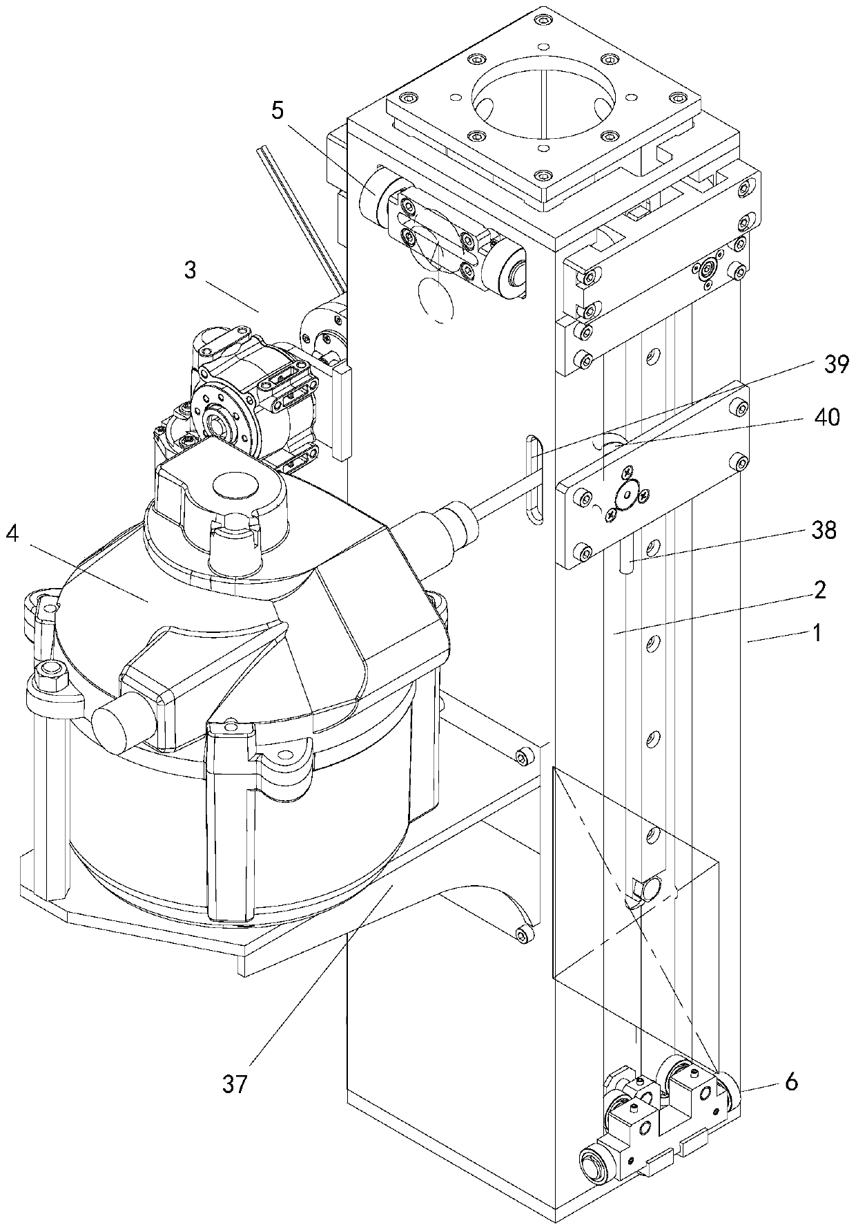
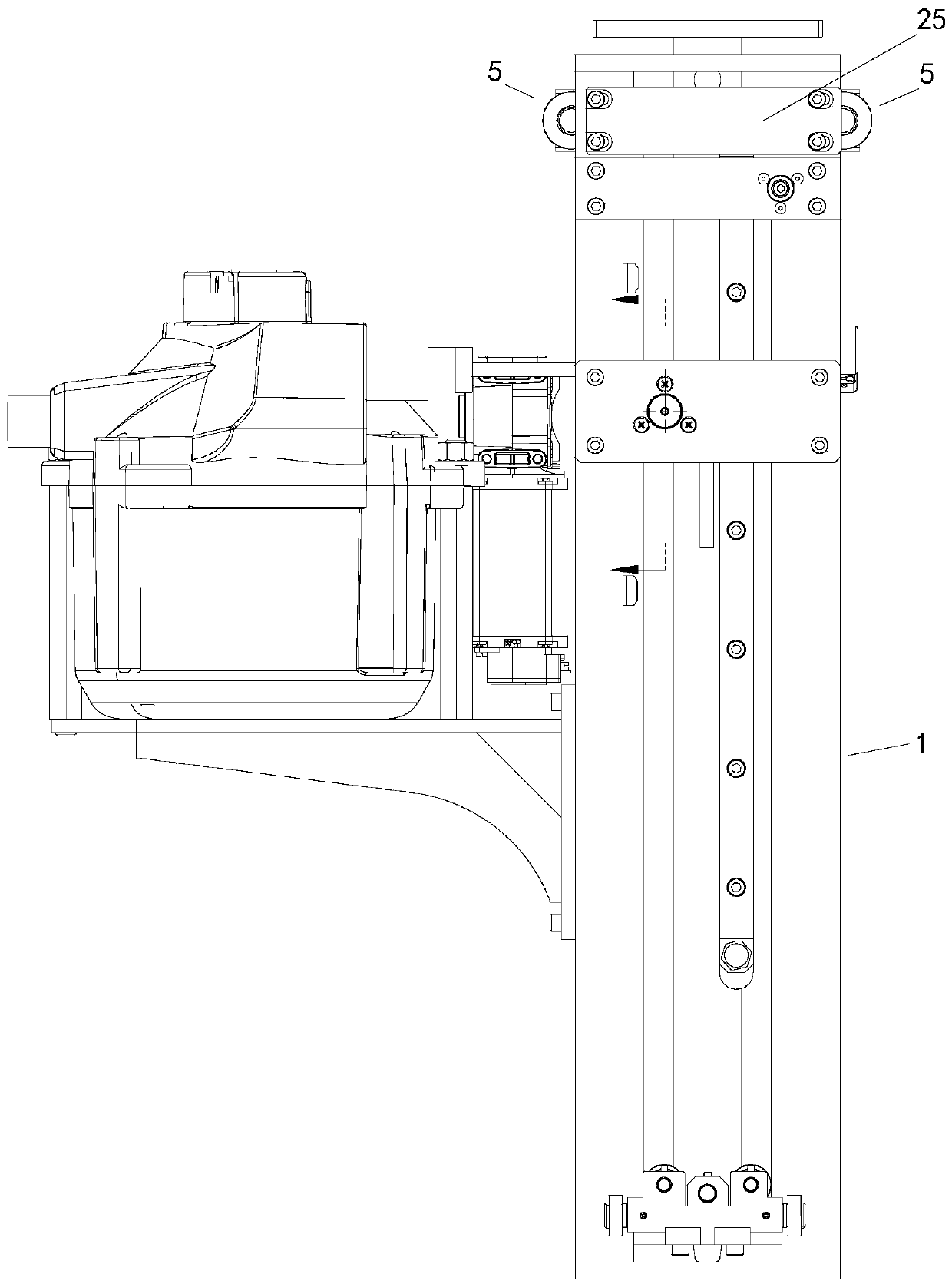
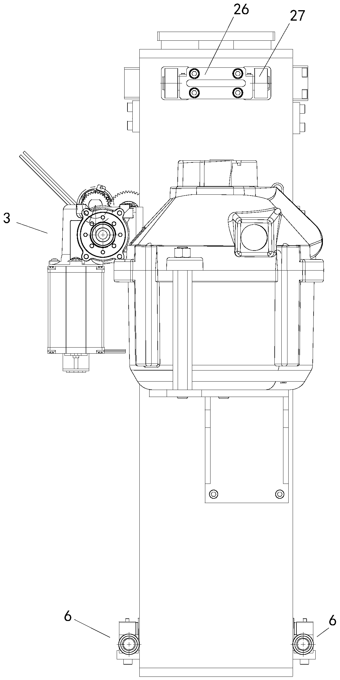
[0045] Such as Figure 1-23 Shown is a vertical lifting column integrating manual and automatic functions, including a lifting column outer cylinder 1 and a lifting column inner cylinder 2, the lifting column inner cylinder is located in the lifting column outer cylinder, and the lifting column outer cylinder and the lifting column inner cylinder There is a guiding mechanism that guides the lifting movement of the inner cylinder of the lifting column, and the ...


PUM


Abstract

The invention relates to a vertical lifting stand column integrating manual operation and automation. The lifting stand column comprises a lifting stand column outer cylinder and a lifting stand column inner cylinder. A guide mechanism is arranged between the lifting stand column outer cylinder and the lifting stand column inner cylinder. A driving mechanism and a balancer are arranged on the lifting stand column outer cylinder. The balancer enables the lifting stand column inner cylinder and borne unbalance loading force bearing to be in a balanced state with balancer tension in the lifting action process of the lifting stand column inner cylinder. The stand column adopts an inner-outer cylinder telescopic structure. The driving mechanism drives the inner cylinder to ascend and descend and passes through the guide mechanism. Accurate movement of the inner cylinder relative to the outer cylinder is realized. The energy storage function of the volute spring of the balancer is applied toovercome the F unbalance loading force bearing with the unbalance distance about 0.8 m. The unbalance loading force bearing and the balancer tension are in a balanced state, so that the functions ofpausing and staying at any position can be realized manually. The energy storage inertia of the balancer volute spring is only about 5% of the rated bearing capacity of the balancer volute spring during electric operation, so that the balancer volute spring is driven by a friction clutch with smaller torque force to stably and accurately move up and down without shaking.

Description

technical field [0001] The invention relates to a vertical lifting column integrating manual and automatic functions used in a non-isocentric mobile three-dimensional C-arm X-ray machine. Background technique [0002] The non-isocentric mobile three-dimensional C-arm X-ray machine products can be widely used in orthopedics, surgery, orthopedics, urology, spinal surgery, abdominal surgery, pain, gastroenterology, gynecology and operating rooms; the so-called non-isocentric mobile The principle of the three-dimensional C-arm X-ray machine is that the center of the C-arm deviates from the focus position of the ray projection image of the object obtained at different angles. In clinical practice, the focus of the ray projection image of the object is always the same The lesion points of the measured objects overlap, and through the three-axis nonlinear linkage form of the equipment, the use of 3D dynamic imaging (30FPS) technology greatly expands the scope of orthopedic surgery ...

Claims


Application Information

Patent Timeline
Patent Type & Authority Applications(China)
IPC IPC(8): A61B6/00
CPCA61B6/44
Inventor 赵正龙赵志浩李丽
Owner 赵正龙
Why Eureka
Try Eureka