
Heat exchanger for thermosiphon

A heat exchanger and thermosiphon technology, applied in heat exchange equipment, indirect heat exchangers, instruments, etc., can solve the problems of fan power consumption, large front cross section, unstable flow, etc., to improve heat dissipation efficiency, large The effect of reducing the effective area and reducing wind resistance

Pending Publication Date: 2020-04-10
锘威科技(深圳)有限公司
View PDF0 Cites 0 Cited by
  • Summary
  • Abstract
  • Description
  • Claims
  • Application Information

AI Technical Summary

Problems solved by technology

Both types of cooling units can only handle low to medium heat flux loads from the CPU, not high heat flux
They are limited by the extremely high pressure drop and high air flow required to work, both of which cause them to draw a lot of fan power, and high fan speeds create a lot of noise
Existing thermosyphon heat exchangers are susceptible to poor thermohydraulic design of the thermosyphon heat exchanger fluid circuit, which creates large flow resistance, resulting in low flow rates and unnecessary flow instabilities; This means they cannot withstand high heat fluxes and are prone to premature dry burning, overheating electronics and erratic start-up
[0003] In addition, the large cross-section at the front due to the prevalent circular piping of the riser, return and distributor pipes of existing thermosyphon heat exchangers blocks much of the available surface area for air flow, resulting in relatively large Large pressure drop, less heat transfer and larger condenser area, thus limiting the lower heat load, and the required fan power consumption is also greater under the same heat load conditions

Method used


Image

  • Heat exchanger for thermosiphon
  • Heat exchanger for thermosiphon
  • Heat exchanger for thermosiphon

Examples


Embodiment Construction

[0041] In order to make the technical problems, technical solutions and beneficial effects to be solved by the embodiments of the present invention clearer, the present invention will be further described in detail below in conjunction with the accompanying drawings and embodiments. It should be understood that the specific embodiments described here are only used to explain the present invention, not to limit the present invention.

[0042] It should be noted that when an element is referred to as being “fixed” or “disposed on” another element, it may be directly on the other element or be indirectly on the other element. When an element is referred to as being "connected to" another element, it can be directly connected to the other element or indirectly connected to the other element. In addition, the connection can be used for both fixing function and circuit communication function.

[0043] It is to be understood that the terms "length", "width", "upper", "lower", "front...


PUM


Abstract

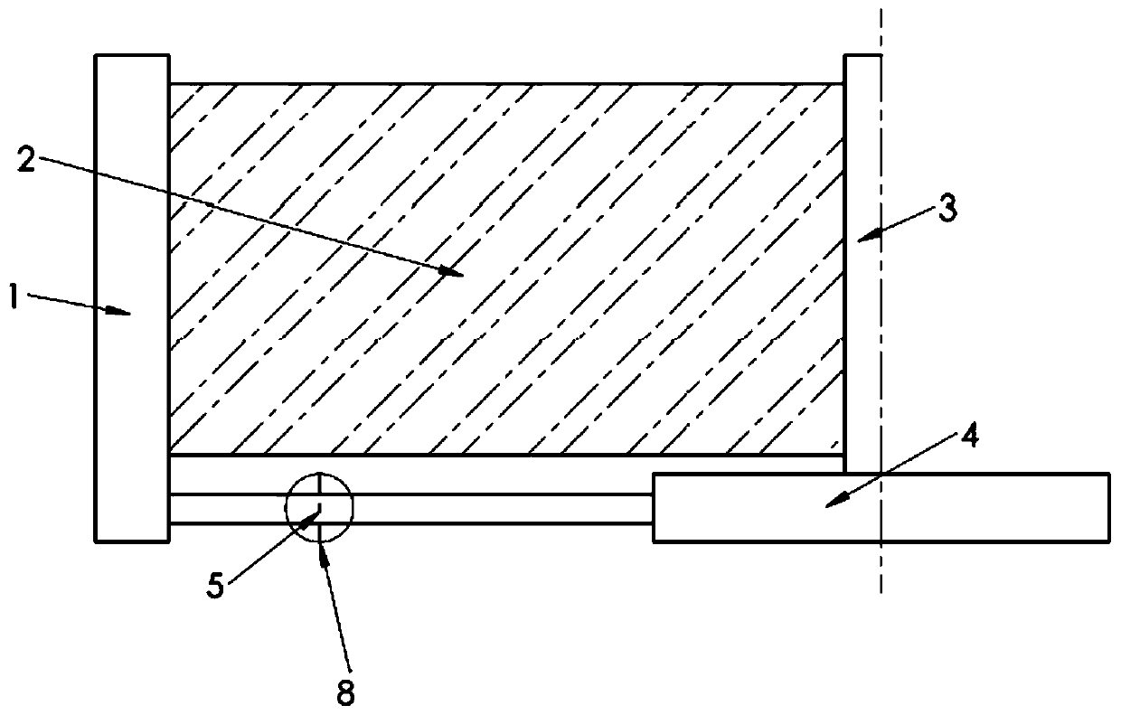
The invention provides a heat exchanger for a thermosiphon. The heat exchanger comprises an evaporator, a flow elevating pipe, a condenser and a flow return pipe, wherein an outlet of the evaporator is connected with an inlet of the flow elevating pipe, an outlet of the flow elevating pipe is connected with an inlet of the condenser, an outlet of the condenser is connected with the top of the flowreturn pipe, fluid of the flow return pipe is downwards conveyed to the inlet of the condenser, the flow elevating pipe and the flow return pipe are rectangular pipes, the evaporator is a micro-channel evaporator, a bottom plate of the micro-channel evaporator is provided with fins, and the condenser comprises at least one flat micro-channel tube. By means of the heat exchanger, the power dissipation is lowered, the effective area of the condenser is maximized, the wind resistance is lowered, and the heat dissipation efficiency is improved.

Description

technical field [0001] The invention relates to the technical field of thermosiphon, in particular to a thermosiphon heat exchanger. Background technique [0002] Existing cooling elements for microprocessor CPUs in data center servers are essentially (i) air cooling units or (ii) air cooling assisted by heat pipe units. Both types of cooling units can only handle low to medium heat flux loads from the CPU, not high heat flux. They are limited by the extremely high pressure drop and high air flow required to work, both of which cause them to consume a lot of fan power, and high fan speeds can generate a lot of noise. Existing thermosyphon heat exchangers are susceptible to poor thermohydraulic design of the thermosyphon heat exchanger fluid circuit, which creates large flow resistance, resulting in low flow rates and unnecessary flow instabilities; This means they cannot withstand high heat fluxes and are prone to premature dry burning, overheating electronics and erratic ...

Claims


Application Information

Patent Timeline
IPC IPC(8): F28D15/02F28F1/02G06F1/20
CPCF28D15/0233F28F1/022G06F1/206
Inventor 约翰·R·托姆张礼政
Owner 锘威科技(深圳)有限公司
Learn More