
Plane wave generator measuring system based on movable array antenna and applied to base station antenna production line

A technology of array antenna and base station antenna, applied in the field of plane wave generator measurement system, can solve the problems of high test distance requirements and high cost of compact field, reduce test field requirements, save equipment cost investment, reduce construction cost and complexity Effect

Active Publication Date: 2020-04-10
BEIHANG UNIV
View PDF13 Cites 8 Cited by
  • Summary
  • Abstract
  • Description
  • Claims
  • Application Information

AI Technical Summary

Problems solved by technology

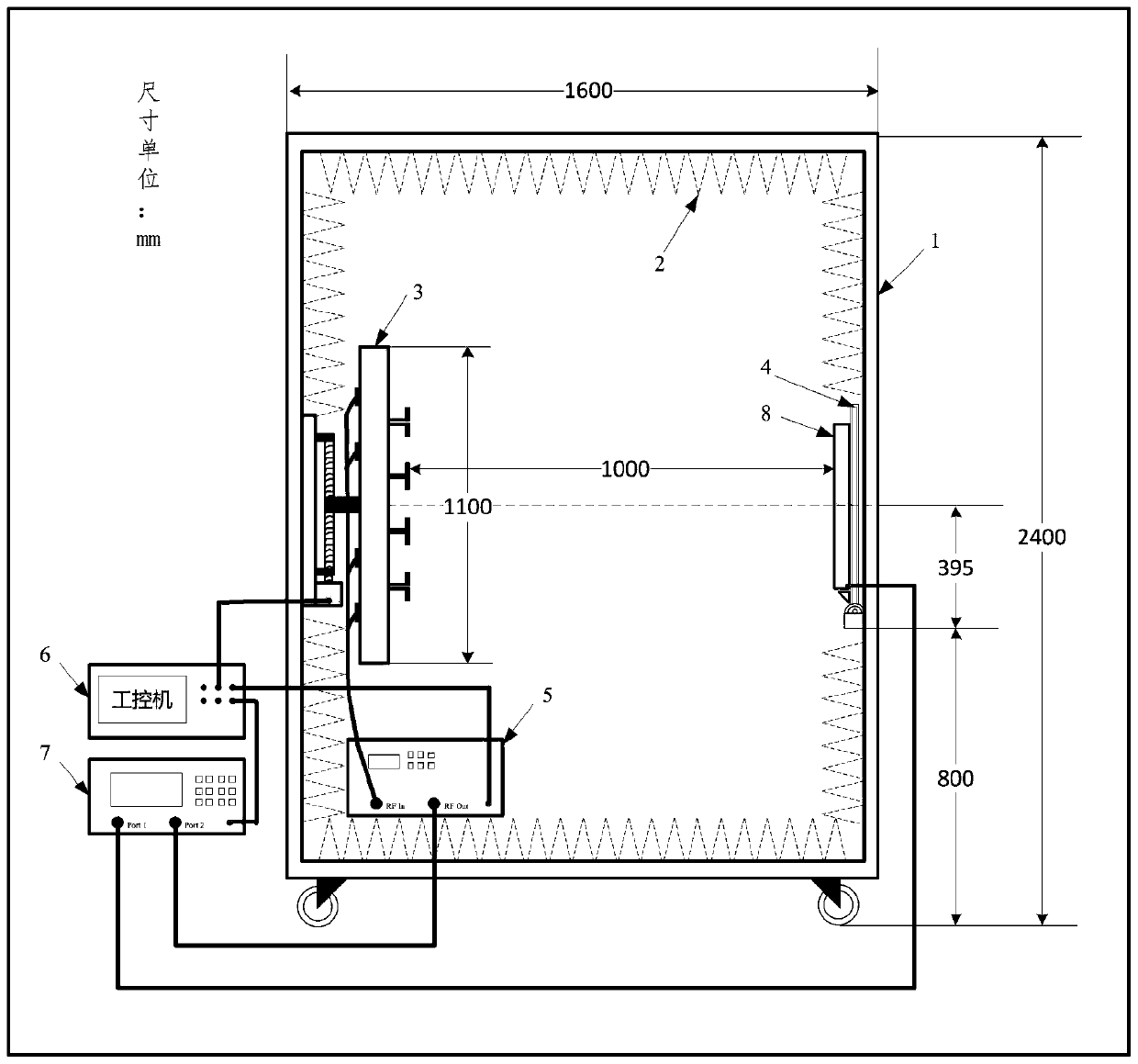
[0007] The technical problem to be solved by the present invention is: to overcome the limitations of the existing antenna system test environment, such as: the cost of the compact field is expensive, and the real far field requires a high test distance, and a mobile array antenna based on the base station is provided. Plane wave generator measurement system for antenna production line. The system has a plane wave generator based on a highly sparse array. The number of array elements is 1 / (N+1)(N≥1) of similar arrays. The system cost and complexity will be reduced to To the minimum, and integrate the entire test system in a dark box of 1.6m*1.6m*2.4m, the black box is convenient for movement and replacement of the tested part; and the system has frequency coverage of a single frequency band or multiple frequency bands and is adjustable, performance Excellent, simple structure, low production cost and difficulty, and easy installation

Method used


Image

  • Plane wave generator measuring system based on movable array antenna and applied to base station antenna production line
  • Plane wave generator measuring system based on movable array antenna and applied to base station antenna production line
  • Plane wave generator measuring system based on movable array antenna and applied to base station antenna production line

Examples


Embodiment Construction

[0045] The present invention will be further described below in conjunction with the accompanying drawings and specific embodiments.

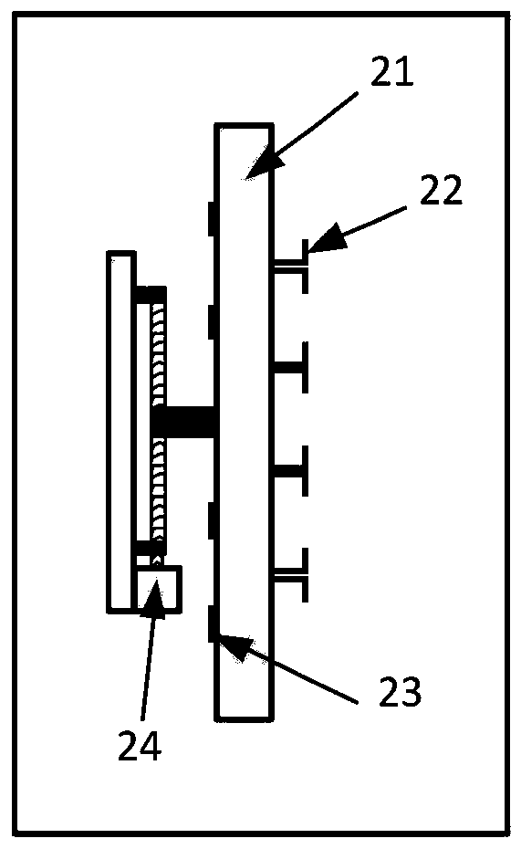
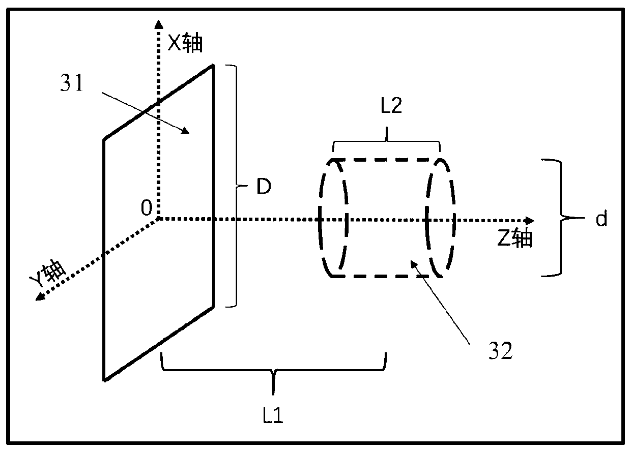
[0046] Such as figure 1 , 2 , 3, the system composition of the present invention and the generated high-quality virtual plane wave quiet zone schematic diagram. The system composition of the present invention includes: black box shielding shell 1, wave-absorbing material and shielding design 2 in the dark box, plane wave generator based on movable array antenna 3, open-close type device under test bracket 4, amplitude modulation and phase modulation network 5, industrial computer 6 (comprising a signal synthesis algorithm), a vector network analyzer 7, and a device under test 8; wherein the specific composition of the plane wave generator 3 based on the movable array antenna is as follows figure 2 As shown, it includes: a two-dimensional array antenna 21 , an array antenna unit 22 , an array antenna feeding network 23 and a transmission meas...


PUM


Abstract

The invention relates to a plane wave generator measuring system based on a movable array antenna and applied to a base station antenna production line. The system comprises a plane wave generator based on a movable array antenna, a shielding camera obscura, a complete wave absorbing material in the camera obscura, a shielding design, an open-close type tested equipment bracket, an amplitude modulation and phase modulation network, an industrial personal computer and a vector network analyzer. A high-quality virtual plane wave dead zone is formed in an area close to the double aperture size ofthe aperture surface of the two-dimensional array antenna by controlling the position of an array antenna unit, the excitation amplitude and phase, adjusting the position of the array antenna for N (N is greater than or equal to 1) times and processing through a signal synthesis algorithm. The plane wave generator is wide in application range, can be used for directional diagram measurement of anelectrically large-size antenna and system radio frequency index measurement with the electrically large-size antenna, and is especially suitable for production line rapid measurement of a base station antenna of 5G mobile communication and measurement of a millimeter wave band terminal antenna and system.

Description

technical field [0001] The present invention relates to the field of electromagnetic field and microwave technology, the field of array antenna technology, the field of antenna and system measurement technology, and the field of automatic control technology, especially the field of 5G mobile communication base station antenna system production line measurement. The specific content is a mobile array antenna based The plane wave generator measurement system applied to the base station antenna production line. Background technique [0002] At present, the research on 5G mobile communication technology and the production of related prototypes have set off a wave of innovation in the mobile communication industry around the world. As one of the key technologies of 5G mobile communication technology, large-scale active antenna array technology has received extensive attention from the industry. The 5G Massive MIMO antenna OTA measurement method is currently a research hotspot in...

Claims


Application Information

Patent Timeline
Patent Type & Authority Applications(China)
IPC IPC(8): G01R29/10G01R29/08
CPCG01R29/0892G01R29/105
Inventor 苗俊刚张雨生
Owner BEIHANG UNIV
Learn More