Spectroscope applied in ocean multi-dimensional imaging system, and preparation method and design method thereof

A technology of an imaging system and a design method, applied in the field of spectroscopes, can solve problems such as poor accuracy and reduced calculation efficiency, and achieve the effect of improving detection efficiency

Active Publication Date: 2020-04-10
中山吉联光电科技有限公司
View PDF7 Cites 1 Cited by
  • Summary
  • Abstract
  • Description
  • Claims
  • Application Information

AI Technical Summary

Problems solved by technology

The envelope curve method has the advantage of high measurement efficiency. It is more accurate when the film absorption is very small, but the accuracy is poor when the film absorption is large; the full spectrum fitting method has a wide range of applications, but when the wavelength band is wide drop sharply

Method used


Image

  • Spectroscope applied in ocean multi-dimensional imaging system, and preparation method and design method thereof
  • Spectroscope applied in ocean multi-dimensional imaging system, and preparation method and design method thereof
  • Spectroscope applied in ocean multi-dimensional imaging system, and preparation method and design method thereof

Examples


Embodiment 1

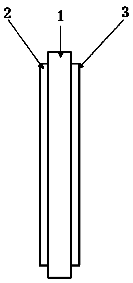
[0085] This embodiment provides a spectroscope used in a marine multi-dimensional imaging system, such as figure 1As shown, the beam splitter includes a substrate, and a first optical film system 2 and a second optical film system 3 respectively deposited on both sides of the substrate 1, the first optical film system 2 is located on the incident light side of the substrate 1 , the second optical film system 3 is located on the light emitting side of the substrate 1;

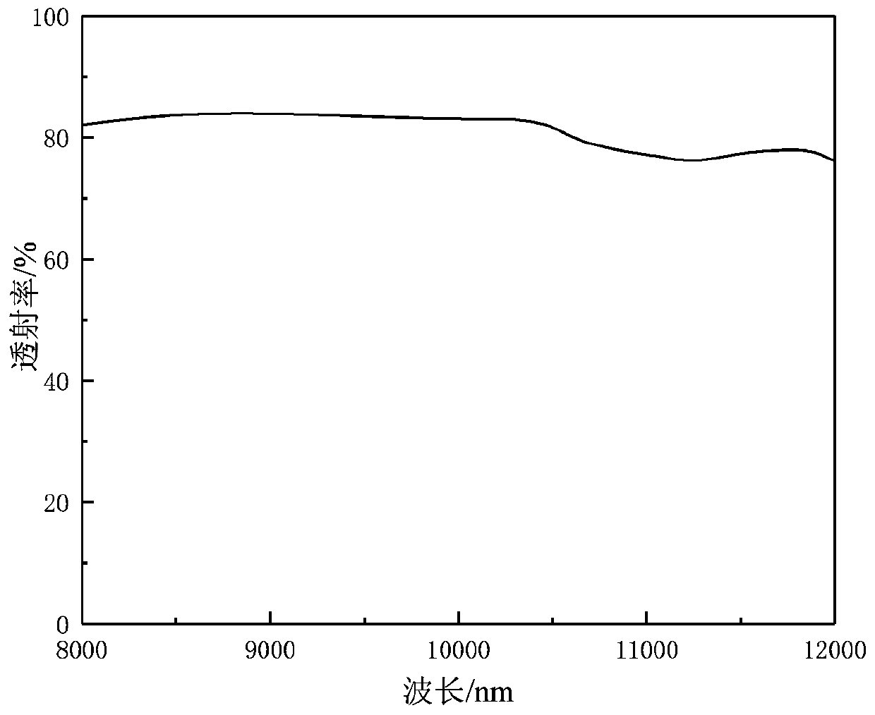
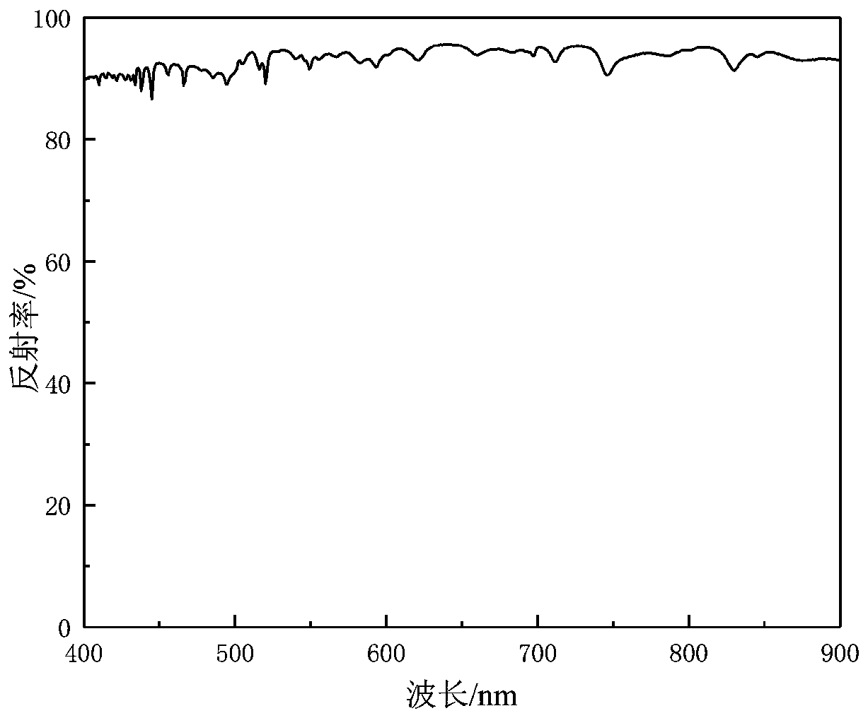
[0086] The basic structure of the first optical film system 2 is Sub|1.4(0.8H(LH) 3 L0.8H) 3 1.1(0.8H(LH) 3 L0.8H) 3 0.9(0.8H(LH) 3 L0.8H) 3 0.7(0.8H(LH) 3 L0.8H) 3 |Air, where H represents M-ZnS with a thickness of λ / 4, and L represents YbF with a thickness of λ / 4 3 , Sub means M-ZnS substrate, Air means air, λ is 550nm, and the total film thickness is 7.2μm. On one side of the multi-spectral zinc sulfide coating (the other side is not coated), the transmittance spectrum in the 2-12 μm band and the tra...

Embodiment 2

[0140] This embodiment designs a beam splitter used in a marine multi-dimensional imaging system, the beam splitter includes a substrate, and a first optical film system and a second optical film system respectively deposited on both sides of the substrate, the first The optical film system is located on the incident light side of the substrate, and the second optical film system is located on the light emitting side of the substrate 1;

[0141] The basic structure of the first optical film system is Sub|2(0.8L(HL) 3 H0.8L) 4 1.8(0.8L(HL) 3 H0.8L) 4 1.5(1.4L(HL) 3 H0.8L) 4 1.0(0.8L(HL) 3 H0.8L) 4 |Air, where H represents M-ZnS with a thickness of λ / 4, and L represents YbF with a thickness of λ / 4 3 , Sub means M-ZnS substrate, Air means air, λ is 550nm, and the total film thickness is 8.26μm. The theoretical spectrum of its front surface is shown in Figure 16.

[0142] The basic structure of the second optical film system is Sub|6.24H8.75L0.34H9.23L|Air, in which the ma...

Embodiment 3

[0144] This embodiment designs a beam splitter used in a marine multi-dimensional imaging system, the beam splitter includes a substrate, and a first optical film system and a second optical film system respectively deposited on both sides of the substrate, the first The optical film system is located on the incident light side of the substrate, and the second optical film system is located on the light emitting side of the substrate;

[0145] The basic structure of the first optical film system is Sub|1.5(0.8H(LH) 3 L0.8H) 5 1.2(0.8H(LH) 3 L0.8H) 5 0.8(0.8H(LH) 3 L0.8H) 5 0.5(0.8H(LH) 3 L0.8H) 5 |Air, where H represents M-ZnS with a thickness of λ / 4, and L represents YbF with a thickness of λ / 4 3 , Sub means M-ZnS substrate, Air means air, λ is 500nm, and the total film thickness is 10.14μm. The theoretical spectrum of the front surface is shown in 18.

[0146] The basic structure of the second optical film system is Sub|6.24H8.75L0.34H9.23L|Air, in which the single l...


PUM

PropertyMeasurementUnit
thicknessaaaaaaaaaa
thicknessaaaaaaaaaa
transmittivityaaaaaaaaaa

Abstract

The invention discloses a spectroscope used in a marine multi-dimensional imaging system. The spectroscope comprises a substrate, and a first optical film system and a second optical film system whichare respectively deposited on two sides of the substrate. The basic structure of the first optical film system is Sub | a (0.8 H (LH)<3>L0. 8H)

b (0.8 H (LH) <3>L0. 8H)

c (0.8 H (LH) <3>L0. 8H)

d (0.8 H (LH) <3>L0. 8H)

| Air and the basic structure of the second optical film system is Sub | 6.24H8. 75L0. 34H9. 23L | Air, wherein the H represents a film layer made of a high-refractive-index material, the L represents a film layer made of a low-refractive-index material, the Sub represents the substrate, the Air represents air, the a, b, c and d represent coefficients relative to a central wavelength, the a is larger than the b larger than the c larger than the d, and the p is an overlapping period number. The spectroscope provided by the invention is wider than a traditional spectroscope in use waveband, efficient reflection of 0.4-0.9 micron is realized and efficient transmission of 8-12 microns is realized, the system detection efficiency is improved, and an in-situ annealing method is also utilized to improve the salt spray resistance of the film.

Description

technical field [0001] The invention relates to the technical field of optical thin films, in particular to a spectroscope used in marine multi-dimensional imaging systems. Background technique [0002] The state of the marine environment around my country is basically stable, but the frequent occurrence of eutrophication, red tides, and oil spills in some sea areas has seriously threatened marine ecological security. The traditional monitoring system mainly relies on shipboard manual sampling and aerial photography, but there are problems of high cost, slow measurement speed and long interval between repeated observations. At the same time, limited by the atmospheric band and weather conditions, the data collected by ocean remote sensing satellites is limited to a small amount of information such as ocean water color and temperature. Low operating costs make it one of the most promising means of rapid detection response. [0003] At present, the commonly used remote sensi...

Claims


Application Information

Patent Timeline
Patent Type & Authority Applications(China)
IPC IPC(8): G02B27/10C23C14/26C23C14/30C23C14/06C23C14/58
CPCC23C14/0629C23C14/0694C23C14/26C23C14/30C23C14/5806G02B27/1006
Inventor 付秀华于雪冰张静
Owner 中山吉联光电科技有限公司
Why Eureka
Try Eureka