Optical fiber conduction green light source and all-fiber laser backlight source device

A light source device and optical fiber technology, which is applied in projection devices, optical waveguide coupling, optics, etc., can solve the problems of small blue light penetration depth, temperature quenching, concentration quenching, etc., and achieve enhanced blue light utilization, increased absorption, The effect of low difficulty of heat treatment

Inactive Publication Date: 2020-04-10
XUZHOU NORMAL UNIVERSITY
View PDF6 Cites 3 Cited by
  • Summary
  • Abstract
  • Description
  • Claims
  • Application Information

AI Technical Summary

Problems solved by technology

However, this method has a small penetration depth of blue light, and the heat is concentrated in a small area. The thermal focusing temperature of the photo-conversion material is extremely high, and there are common problems of temperature quenching and concentration quenching, which eventually cause luminescence quenching or even failure.

Method used


Image

  • Optical fiber conduction green light source and all-fiber laser backlight source device
  • Optical fiber conduction green light source and all-fiber laser backlight source device
  • Optical fiber conduction green light source and all-fiber laser backlight source device

Examples


Embodiment 1

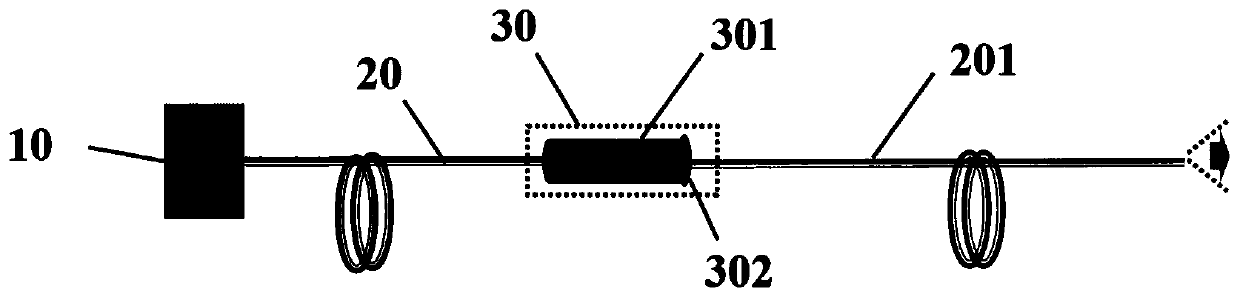
[0026] A kind of optical fiber transmission green light source device, such as figure 1 As shown, it includes blue laser one 10, optical fiber one 20, fluorescent converter 30 and optical fiber two 201 connected in sequence. The fluorescent converter 30 includes a transparent fluorescent ceramic rod 301 and a coupling focusing lens 302, and the coupling focusing lens 302 is located at The transparent fluorescent ceramic rod 301 is connected to one end of the second optical fiber 201 .

[0027] The transparent fluorescent ceramic rod 301 is cerium-doped lutetium aluminum garnet (Ce:Lu 3 Al 5 o 12 , Ce:LuAG) transparent ceramics, Ce 3+ The doping concentration is 0.01 at%, and the transmittance of the transparent ceramic in the green light band is 60.0%. The transparent fluorescent ceramic rod 301 is cylindrical, with an end radius of 0.5 mm and a length of 6.0 mm. For the preparation of transparent ceramics, refer to the preparation process disclosed in patent application C...

Embodiment 2

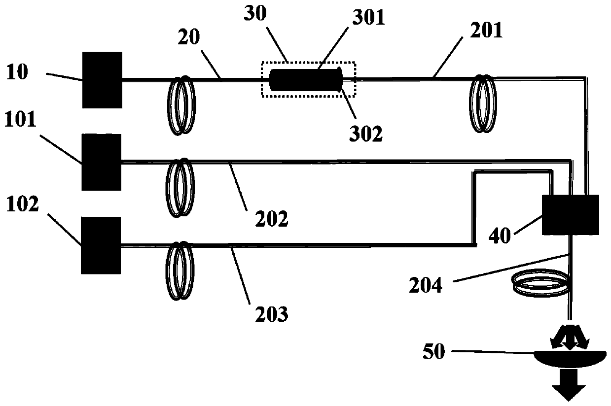
[0030] An all-fiber laser backlight device, such as figure 2 As shown, including the fiber-optic transmission green light source device of embodiment 1, blue laser 2 101, red laser 102, optical fiber 3 202, optical fiber 4 203, optical fiber 5 204, optical fiber beam combiner 40, focusing and collimating mirror 50, all The blue laser 2 101 is connected to the optical fiber 3 202, the red laser 102 is connected to the optical fiber 4 203, the optical fiber 201, the optical fiber 3 202, and the optical fiber 203 of the green light source device are combined and inserted into the optical fiber combiner 40, The other end of the optical fiber combiner 40 outputs the optical fiber five 204 , and the focusing and collimating mirror 50 is installed at the end of the optical fiber five 204 .

[0031]When the output power of the blue laser-10 is 2W, the operating temperature of the transparent fluorescent ceramic rod 301 is 70°C; the end can obtain 300lm green light, and the luminous e...

Embodiment 3

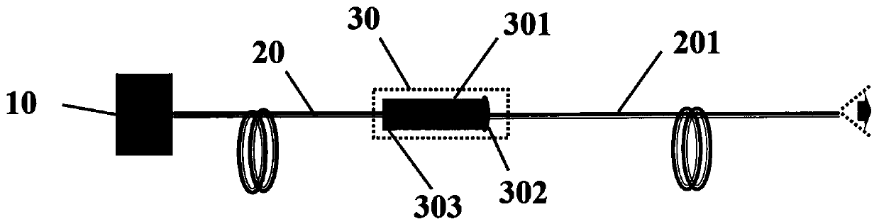
[0034] A kind of optical fiber transmission green light source device, such as image 3 As shown, it includes blue laser one 10, optical fiber one 20, fluorescent converter 30 and optical fiber two 201 connected in sequence. The fluorescent converter 30 includes a transparent fluorescent ceramic rod 301, a coupling focusing lens 302 and a dichroic film 303. The coupling The focusing lens 302 is located at one end of the transparent fluorescent ceramic rod 301 connected to the second optical fiber 201 , and the dichroic film 303 is located at the end of the transparent fluorescent ceramic rod 301 connected to the first optical fiber 20 .

[0035] The transparent fluorescent ceramic rod 301 is cerium-doped lutetium aluminum garnet (Ce:Lu 3 Al 5 o 12 , Ce:LuAG) transparent ceramics, Ce 3+ The doping concentration is 0.50 at%, and the transmittance of the transparent ceramic in the green light band is 80.0%. The transparent fluorescent ceramic rod 301 is cylindrical, with an en...


PUM

PropertyMeasurementUnit
lengthaaaaaaaaaa
luminous efficiencyaaaaaaaaaa
wavelengthaaaaaaaaaa

Abstract

The invention discloses an optical fiber conduction green light source and an all-fiber laser backlight source device. The green light source device comprises a blue laser I, an optical fiber I, a fluorescence converter and an optical fiber II which are connected in sequence, the all-fiber laser backlight source device comprises the above optical fiber conduction green light source device, a second blue light laser, a red light laser, a third optical fiber, a fourth optical fiber, a fifth optical fiber, an optical fiber beam combiner and a focusing collimating mirror. The second blue laser isconnected with the third optical fiber, the red laser is connected with the fourth optical fiber, and the second optical fiber, the third optical fiber and the fourth optical fiber of the green lightsource device are jointly combined and inserted into the optical fiber beam combiner. The other end of the optical fiber beam combiner outputs the fifth optical fiber, and the tail end of the fifth optical fiber is provided with the focusing collimating mirror. According to the green light source device, the green light luminous intensity and the conversion efficiency are improved, and the laser backlight source device is low in production cost, good in device thermal management and high in projection quality.

Description

technical field [0001] The invention relates to the technical field of laser display, in particular to an optical fiber transmission green light source and an all-fiber laser backlight source device. Background technique [0002] Laser display technology (Laser Display Technique, LDT) has significant advantages such as rich colors, high saturation, and strong contrast, and is widely considered to be the mainstream technology for future high-end displays such as large-screen projection, laser TV, digital cinema, and mobile phone projection. [0003] The core of laser display technology has two parts, 1) imaging technology; 2) light source technology. Among them, the core imaging devices are dominated by the United States and Japan, and domestic researchers still need further research; among the light source technologies, the most satisfactory is the red, green and blue three-color laser diode (Laser Diodes, 3LD) projection technology, such as the patent CN207216255U , respec...

Claims


Application Information

Patent Timeline
Patent Type & Authority Applications(China)
IPC IPC(8): G03B21/20G02B6/32G03B21/16
CPCG02B6/32G03B21/16G03B21/204G03B21/208
Inventor 张乐康健陈东顺孙炳恒周天元陈浩
Owner XUZHOU NORMAL UNIVERSITY
Why Eureka
Try Eureka