Design method of diffractive optical element with high diffraction efficiency and low speckle noise

A diffractive optical element and diffraction efficiency technology, applied in the design field of diffractive optical elements, can solve the problems of serious speckle noise, low diffraction efficiency, quantization error, etc., and achieve low speckle noise, high diffraction efficiency, and suppression of quantization error. Effect

Inactive Publication Date: 2020-04-14
INST OF OPTICS & ELECTRONICS - CHINESE ACAD OF SCI
View PDF32 Cites 3 Cited by
  • Summary
  • Abstract
  • Description
  • Claims
  • Application Information

AI Technical Summary

Problems solved by technology

[0006] The technical problem to be solved by the present invention is to overcome the problems of low diffraction efficiency and serious speckle noise caused by quantization errors in the design of diffractive optical elements

Method used


Image

  • Design method of diffractive optical element with high diffraction efficiency and low speckle noise
  • Design method of diffractive optical element with high diffraction efficiency and low speckle noise
  • Design method of diffractive optical element with high diffraction efficiency and low speckle noise

Examples


Embodiment Construction

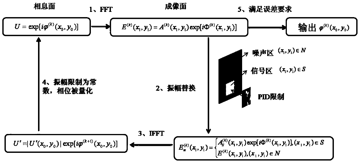
[0046] The present invention will be described in detail below in conjunction with the accompanying drawings and specific embodiments. The protection scope of the present invention should include all content of the claims. Through the following examples, those skilled in the art can realize all the contents of the claims of the present invention.

[0047] figure 1 Flowchart for the design of diffractive optical elements with high diffraction efficiency and low speckle noise, such as figure 1 Shown, the design method step of the present invention is as follows:

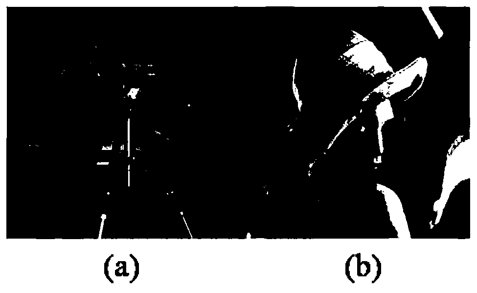
[0048] Step (1), the wavelength of the laser used in the diffraction element design is a plane wave of λ=650nm, select figure 2 (a) and (b) as the light intensity distribution I of the target light field d (x 1 ,y 1 ), where the target light field amplitude distribution

[0049] Step (2), using Fast Fourier Transform FFT as the diffraction propagation function;

[0050] Step (3), the number of phase steps of...


PUM

PropertyMeasurementUnit
refractive indexaaaaaaaaaa

Abstract

The invention discloses a design method of a diffractive optical element with high diffraction efficiency and low speckle noise. The design method comprises the following steps: 1) taking a complex amplitude light field of which the amplitude is a constant amplitude and the phase is a random phase as an initial complex amplitude light field on a kinoform surface; 2) spreading the complex amplitudelight field on the kinoform to an imaging surface through diffraction, and obtaining a complex amplitude light field on the imaging surface; 3) replacing the amplitude part of the complex amplitude light field obtained in the step 2) with specially designed PID limitation; 4) reversely diffracting and propagating the replaced complex amplitude light field in the step 3) back to the kinoform surface to obtain a complex amplitude light field; 5) taking out the phase part of the complex amplitude light field in the step 4), and quantifying the phase part to obtain the phase of a diffractive optical element; (6) taking the phase obtained in the step (5) as the phase of the kinoform surface, and taking the constant amplitude as the amplitude of the kinoform surface to obtain a complex amplitude light field of the kinoform surface, and (7) repeating the step (2) and the step (6), and completing iteration when the diffractive optical element meets the design requirements.

Description

technical field [0001] The invention belongs to the field of applied optics, and in particular relates to a design method of a diffractive optical element with high diffraction efficiency and low speckle noise. Background technique [0002] A diffractive optical element (DOE) is a device with a surface micro-nano structure, which can generate a phase difference to the incident light irradiated on its surface, thereby realizing the wavefront modulation of the incident light. DOE has the advantages of miniaturization, integration, and multi-function, and can greatly reduce the volume of the optical system. It has been widely used in AR, VR, optical tweezers, beam splitters, beam shaping, laser processing, spectral analysis, and holographic display. and other fields. The DOE design process is a phase recovery process. Using the phase recovery algorithm, the wavefront distribution of the target light field can be calculated, that is, phase holography, and then the surface micr...

Claims


Application Information

Patent Timeline
Patent Type & Authority Applications(China)
IPC IPC(8): G02B27/00G02B5/32
CPCG02B27/0012G02B5/32
Inventor 邓启凌庞应飞庞辉史立芳曹阿秀
Owner INST OF OPTICS & ELECTRONICS - CHINESE ACAD OF SCI
Why Eureka
Try Eureka