
Uniform weld joint welding device

A welding device and uniform technology, applied in welding equipment, welding accessories, electrode support devices, etc., can solve the problems of poor weld controllability and achieve the effects of increasing deposition rate, improving thermal efficiency, and improving control flexibility

Pending Publication Date: 2020-04-17
CHONGQING GAS COMPRESSOR FACTORY
View PDF6 Cites 0 Cited by
  • Summary
  • Abstract
  • Description
  • Claims
  • Application Information

AI Technical Summary

Problems solved by technology

[0004] However, although the speed of TIG welding has been increased, the traditional method of droplet transfer is still used, that is, the droplet is formed first and then transferred to the molten pool, and the controllability of the weld is poor.

Method used


Image

  • Uniform weld joint welding device

Examples


Embodiment Construction

[0016] The following is further described in detail through specific implementation methods:

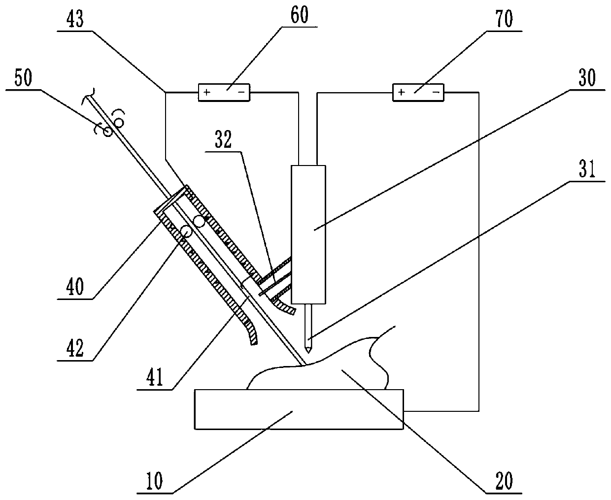
[0017] The reference signs in the drawings of the description include: base material 10, molten pool 20, tungsten welding gun 30, main tungsten wire 31, branch tungsten wire 32, welding wire welding gun 40, welding wire 41, guide wheel 42, coil 43, wire feeding mechanism 50 , the second power source 60 , and the first power source 70 .

[0018] The embodiment is basically as attached figure 1 Shown: a uniform seam welding device, the base material 10 molten pool 20 is at the bottom. On the upper left of the base material 10 is a welding wire welding torch 40, which is installed obliquely on the frame, and above the welding torch is a wire feeding mechanism 50, and the wire feeding mechanism 50 can be a traditional machine feeding mechanism. On the upper right of the base material 10 is the tungsten electrode welding torch 30 , and on the upper right are the first power source 70 an...


PUM


Abstract

The invention belongs to the field of welding, and particularly relates to a uniform weld joint welding device. The uniform weld joint welding device comprises a base material, a tungsten electrode welding gun, a welding wire welding gun, a first power source and a wire feeding mechanism used for conveying welding wires, the first power source is connected between the tungsten electrode welding gun and the base material, and the uniform weld joint welding device further comprises a second power source, wherein a branch pipe is arranged on the tungsten electrode welding gun, the branch pipe isin communication with the welding wire welding gun, a branch tungsten wire is arranged on a main tungsten wire of the tungsten electrode welding gun, and the branch tungsten wire is located in the branch pipe; a coil is arranged in the side wall of the welding wire welding gun, one end of the coil is connected with the tungsten electrode welding gun through the second power source, and the other end of the coil is in sliding connection with the welding wire. Compared with a traditional welding device, according to the scheme, a traditional molten drop transition mode is avoided, the welding wire can be directly inserted into the molten pool, almost no distance exists between the welding wire and a molten pool, and after a coupling electric arc is formed, people can control variables through parameters such as welding current, voltage, welding speed and wire feeding speed, and the controllability of the weld joint is greatly improved.

Description

technical field [0001] The invention belongs to the field of welding, and in particular relates to a uniform seam welding device. Background technique [0002] Under the development requirements of welding automation and artificial intelligence, further increasing the welding speed is an important way to improve welding productivity. In general, the filler wire is fed under cold conditions. In order to improve the deposition speed and production efficiency of the weld, TIG welding can be performed with preheated wire. [0003] For example, the patent No. 201220075933.3 discloses a high-speed welding device with dual power sources and double electrodes, including argon tungsten arc welding torch (1), gas metal arc welding torch (2), argon tungsten arc welding machine welding power supply ( 3), MIGA welding power supply (5), MIGA welding machine ground wire (6), molten pool (7) and base metal (8), MIMA welding machine welding power supply (5) The positive pole of the argon t...

Claims


Application Information

Patent Timeline
Patent Type & Authority Applications(China)
IPC IPC(8): B23K9/167B23K9/02B23K9/28B23K9/133B23K9/095B23K9/32
CPCB23K9/167B23K9/02B23K9/28B23K9/133B23K9/095B23K9/32
Inventor 车佳益刘斌石德勋李德华李成保向传杰董稹曹林国
Owner CHONGQING GAS COMPRESSOR FACTORY
Learn More