
Feeding assembly of motor shaft hole processing equipment

A hole processing and motor shaft technology, applied in the field of motor shaft hole processing equipment feeding components, can solve the problems of low efficiency, inability to guarantee the finished product rate of processed parts, and high labor intensity, so as to reduce the scrap rate, reduce labor intensity, The effect of improving productivity

Pending Publication Date: 2020-04-17
丹东富田精工机械有限公司
View PDF0 Cites 3 Cited by
  • Summary
  • Abstract
  • Description
  • Claims
  • Application Information

AI Technical Summary

Problems solved by technology

[0009] Aiming at the problems in the prior art that the machining of the taper hole at the tail end of the motor shaft product is performed manually, the finished product rate of the workpiece cannot be guaranteed, the labor intensity is high, and the efficiency is low. The problem to be solved by the present invention is to provide a method that can replace the traditional Motor shaft hole processing equipment with manual operation and greatly improved work efficiency

Method used


Image

  • Feeding assembly of motor shaft hole processing equipment
  • Feeding assembly of motor shaft hole processing equipment
  • Feeding assembly of motor shaft hole processing equipment

Examples


Embodiment Construction

[0027] The present invention will be further elaborated below in conjunction with the accompanying drawings of the description.

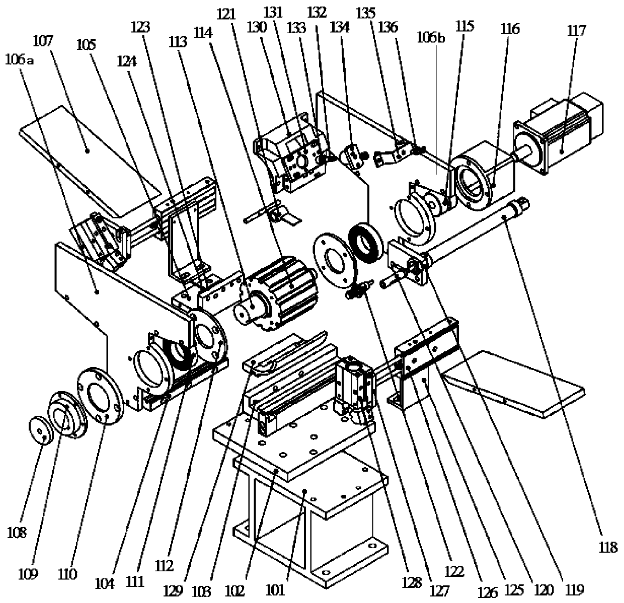
[0028] Such as Figure 2-5 As shown, the feeding assembly of a motor shaft hole processing equipment in the present invention includes a base 101, a V-shaped groove guide rail 104, a pushing cylinder 118, a threaded cylinder 122, a servo motor 117, and a feeding cylinder 126, wherein the base 101 is fixed on the bed body On the table, a V-shaped groove guide rail 104 is installed on the base 101 through the base plate 102 and the guide rail seat 103; the guide rail seat 103 is also fixed with an optical fiber support 105, and an optical fiber connecting plate 123 and an optical fiber sensor 124 are installed on the optical fiber support 105; the two sides of the optical fiber support 105 The first to second brackets 106a to 106b are respectively installed, the silo bottom plate 107 is fixed in the middle of the first to second brackets 106a to 106b ...


PUM


Abstract

The invention discloses a feeding assembly of motor shaft hole processing equipment. A pedestal is fixed to the table surface of a machine body, and provided with a V groove guide rail; a guide rail seat is fixedly provided with an optical fiber bracket which is provided with an optical fiber connecting plate and an optical fiber sensor; the both sides of the optical fiber bracket are provided with first and second brackets separately, and a bottom plate of a stock bin is fixed between the first and second brackets to form a hopper; a workpiece is arranged on the bottom plate of the stock bin;a servo motor is installed on the bracket on one side of the optical fiber bracket through a motor support seat, and an output shaft of the servo motor is provided with a material splitting wheel through a coupling and a rotating shaft; the end faces of the both sides of the material splitting wheel are provided with striker plates, and the front end of the rotating shaft is installed on the first bracket through a bearing, and pressed through a shaft end pressing plate, a bearing gland and an end cover; and a material pushing cylinder is fixed to the guide rail seat through a material pushing cylinder seat, and the front end of the material pushing cylinder is provided with a pushing rod and a threaded cylinder through a connecting rod. According to the feeding assembly, a traditional manual feeding operation method is replaced, and the feeding is accurate and in place; and the labor intensity of operating personnel is reduced, and the reject rate is reduced.

Description

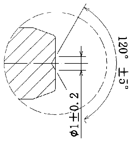
technical field [0001] The invention relates to a feeding device of processing equipment, in particular to a feeding assembly of motor shaft hole processing equipment. Background technique [0002] The motor shaft is an important part of the motor product. The machining accuracy and quality of the motor shaft directly affect the overall quality and service life of the motor. As shown in Figures 1 and 2, the taper hole at the tail of the traditional motor shaft product is usually processed by ordinary lathe through manual operation, which requires manual loading into the fixture, which has poor stability, low efficiency, and is prone to waste, which leads to High scrap rate, low processing precision, high labor intensity and other deficiencies. [0003] With the development of science and technology, automatic processing is applied to the processing technology of various mechanical parts, which greatly improves the processing accuracy, especially the processing of the taper ...

Claims


Application Information

Patent Timeline
IPC IPC(8): B23Q7/00B23Q7/04B23Q7/18
CPCB23Q7/00B23Q7/04B23Q7/18
Inventor 田川任孝权
Owner 丹东富田精工机械有限公司
Learn More