
Optical fiber composite insulator prefabricated core rod, mold and manufacturing method of optical fiber composite insulator prefabricated core rod

An optical fiber composite and insulator technology, applied in insulators, electrical components, circuits, etc., can solve the problems of air bubbles, affecting the performance and service life of optical fiber composite insulators, and achieve the effect of simple steps and solving interface problems.

Active Publication Date: 2020-04-17
SOUTH CHINA UNIV OF TECH
View PDF11 Cites 5 Cited by
  • Summary
  • Abstract
  • Description
  • Claims
  • Application Information

AI Technical Summary

Problems solved by technology

[0004] The purpose of the present invention is to at least solve one of the technical problems in the prior art, to provide a prefabricated core rod, mold and manufacturing method of an optical fiber composite insulator, and to overcome the serious air bubble defect caused by the fiber bonding process when the optical fiber composite insulator is manually manufactured. Problems Affecting the Performance and Service Life of Optical Fiber Composite Insulators

Method used


Image

  • Optical fiber composite insulator prefabricated core rod, mold and manufacturing method of optical fiber composite insulator prefabricated core rod
  • Optical fiber composite insulator prefabricated core rod, mold and manufacturing method of optical fiber composite insulator prefabricated core rod
  • Optical fiber composite insulator prefabricated core rod, mold and manufacturing method of optical fiber composite insulator prefabricated core rod

Examples


Embodiment Construction

[0032] This part will describe the specific embodiment of the present invention in detail, and the preferred embodiment of the present invention is shown in the accompanying drawings. Each technical feature and overall technical solution of the invention, but it should not be understood as a limitation on the protection scope of the present invention.

[0033] In the description of the present invention, it should be understood that the orientation descriptions, such as up, down, front, back, left, right, etc. indicated orientations or positional relationships are based on the orientations or positional relationships shown in the drawings, and are only In order to facilitate the description of the present invention and simplify the description, it does not indicate or imply that the device or element referred to must have a specific orientation, be constructed and operated in a specific orientation, and thus should not be construed as limiting the present invention.

[0034] I...


PUM


Abstract

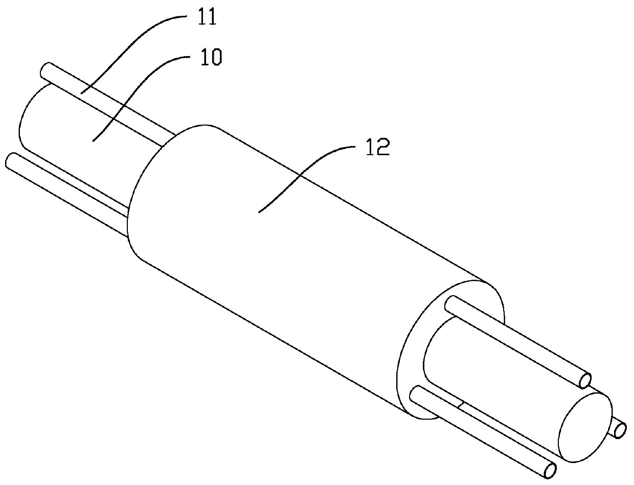
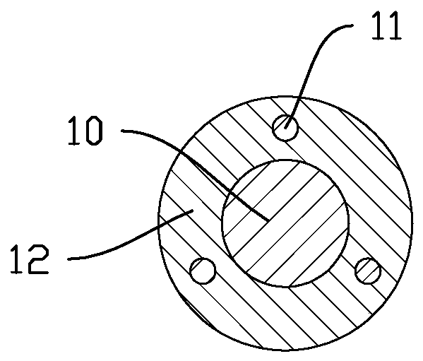
The invention discloses an optical fiber composite insulator prefabricated core rod, a mold and a manufacturing method of the optical fiber composite insulator prefabricated core rod. The optical fiber composite insulator prefabricated core rod comprises a core rod body, a silicone rubber layer and at least one optical fiber. The silicone rubber layer is integrally formed on the outer cylindricalsurface of the core rod body in an injection molding mode, and the silicone rubber layer is annular; at least one optical fiber is arranged outside the core rod body, the middle of the optical fiber is embedded in the silicone rubber layer, and one end or two ends of the optical fiber extends / extend out of the rubber layer. The optical fiber and the core rod body are fixed through vacuum injectionmolding of silicone rubber to form a silicone rubber outer coating layer, air gaps are prevented from being generated on the interfaces of the optical fiber, the silicone rubber layer and the core rod, and the problem that the performance and the service life of the optical fiber composite insulator are seriously affected due to bubble defects generated in the optical fiber bonding process duringmanual manufacturing of the optical fiber composite insulator can be overcome.

Description

technical field [0001] The invention relates to the field of on-line monitoring of power transmission and transformation equipment, in particular to an optical fiber composite insulator prefabricated core rod, a mold and a manufacturing method thereof, which are suitable for optical fiber composite insulators above 110kV. Background technique [0002] The insulator is one of the key equipment in the power system, and its working status affects the safe operation of the power grid. Composite insulators are widely used in my country's power grid lines, and can be divided into rod-shaped suspension composite insulators and line post composite insulators. The rod-shaped composite insulator has a light and simple structure, convenient manufacturing process, strong tensile strength resistance, non-breakdown, and excellent pollution resistance. The line post composite insulator has a relatively fixed shape, simple overall structure, strong bending load capacity, non-breakdown, and...

Claims


Application Information

Patent Timeline
IPC IPC(8): H01B17/38H01B19/00
CPCH01B17/38H01B19/00
Inventor 郝艳捧黄磊韦杰阳林
Owner SOUTH CHINA UNIV OF TECH
Learn More