
Printed circuit substrate with high-precision rectangular positioning microgrooves and manufacturing method

A technology of circuit substrate and manufacturing method, which is applied in the direction of printed circuit manufacturing, printed circuit, printed circuit, etc., can solve the problems of unguaranteed spacing accuracy of positioning micro-grooves, large cumulative error, and decreased yield rate, so as to reduce stress and reduce Effects of transmission loss and reliability improvement

Active Publication Date: 2020-04-17
NO 30 INST OF CHINA ELECTRONIC TECH GRP CORP
View PDF11 Cites 0 Cited by
  • Summary
  • Abstract
  • Description
  • Claims
  • Application Information

AI Technical Summary

Problems solved by technology

No matter which of the above methods is adopted, due to the inherent positioning error of mechanical equipment (the cumulative positioning error of a certain type of equipment in the axial direction of the full stroke reaches 20 μm), as the number of bare optical fiber positioning micro-groove channels increases, the cumulative error will increase, and the positioning micro- The accuracy of the groove spacing cannot be guaranteed, the yield rate will drop, and the cost will increase

Method used


Image

  • Printed circuit substrate with high-precision rectangular positioning microgrooves and manufacturing method
  • Printed circuit substrate with high-precision rectangular positioning microgrooves and manufacturing method
  • Printed circuit substrate with high-precision rectangular positioning microgrooves and manufacturing method

Examples


Embodiment Construction

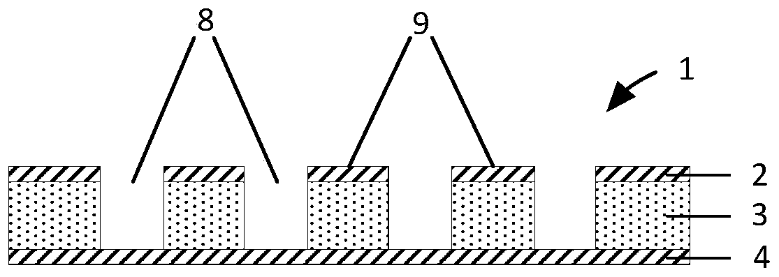
[0028] A printed circuit substrate with high-precision rectangular positioning microgrooves, such as figure 1 As shown, it includes a printed circuit substrate 1; the printed circuit substrate 1 includes a base material layer 3, a first copper foil layer 2 and a second copper foil layer 4 arranged on the opposite surface of the base material layer; The first copper foil layer 2 is provided with several uniformly distributed rectangular openings 7 (such as Figure 7 shown), the rectangular opening penetrates the first copper foil layer 2 and the substrate layer 3 to the upper surface of the second copper foil layer 4 to form a rectangular positioning microgroove 8 (such as Figure 9 shown), the depth and width of the rectangular positioning microgroove 8 are slightly larger than the diameter of the bare optical fiber 10, to ensure that a bare optical fiber can be fully accommodated (such as figure 2 As shown), two adjacent rectangular positioning microgrooves are separated by...


PUM

PropertyMeasurementUnit
thicknessaaaaaaaaaa
thicknessaaaaaaaaaa

Abstract

The invention discloses a printed circuit substrate with high-precision rectangular positioning microgrooves and a manufacturing method. The printed circuit substrate comprises a base material layer and a first copper foil layer and a second copper foil layer which are arranged on the opposite surfaces of the base material layer. A plurality of rectangular openings which are uniformly distributedare formed in the first copper foil layer and penetrate through the first copper foil layer and the base material layer to the upper surface of the second copper foil layer to form rectangular positioning microgrooves capable of completely accommodating one bare optical fiber; every two adjacent rectangular positioning microgrooves are spaced by a ridge, and each ridge is composed of a first copper foil layer and a base material layer. The side walls of the rectangular positioning microgrooves are perpendicular to the surface of the printed circuit substrate. The copper foil of the opening layer can block laser energy and ensure that the side wall of the base material layer is not ablated in the laser etching process so that high-precision rectangular positioning microgrooves are manufactured, the interval precision of the positioning microgrooves is ensured, and the coupling efficiency of a bare fiber array and a photoelectric chip array is improved.

Description

technical field [0001] The invention relates to a printed circuit substrate with high-precision rectangular positioning micro-grooves and a manufacturing method. Background technique [0002] With the rapid increase in the integration level and operating frequency of electronic equipment, the electrical interconnection method based on metal copper can no longer transmit signals efficiently. In the case of high frequency, it will bring serious signal delay and crosstalk, limited bandwidth, and sharp increase in power consumption, which has become a bottleneck for the rapid development of electronic equipment. The optical fiber is embedded in the substrate of the printed circuit board to form a photoelectric interconnection circuit, and the use of optical interconnection instead of electrical interconnection can realize the information transmission between functional units in the electronic equipment system, and can eliminate the technical bottleneck encountered in information...

Claims


Application Information

Patent Timeline
Patent Type & Authority Applications(China)
IPC IPC(8): H05K1/18H05K3/06H05K3/00G02B6/42
CPCH05K1/183H05K3/06H05K3/0026G02B6/428H05K2201/10121H05K2203/107
Inventor 毛久兵许梦婷杨伟杨剑刘强秦宗良杨唐绍冯晓娟
Owner NO 30 INST OF CHINA ELECTRONIC TECH GRP CORP
Learn More