
Navigation device for cortical bone screw in minimally invasive spine surgery

A minimally invasive surgery and navigation device technology, applied in the field of medical equipment, can solve problems such as inconvenient use and poor positioning accuracy, and achieve the effects of avoiding poor positioning, improving accuracy, and avoiding damage

Pending Publication Date: 2020-04-21
BEIJING CHAOYANG HOSPITAL CAPITAL MEDICAL UNIV
View PDF0 Cites 0 Cited by
  • Summary
  • Abstract
  • Description
  • Claims
  • Application Information

AI Technical Summary

Problems solved by technology

[0003] The purpose of the present invention is to provide a navigation device for cortical bone screws in minimally invasive spinal surgery to solve the problems of poor positioning accuracy and inconvenient use of current cortical bone screw locators

Method used


Image

  • Navigation device for cortical bone screw in minimally invasive spine surgery
  • Navigation device for cortical bone screw in minimally invasive spine surgery
  • Navigation device for cortical bone screw in minimally invasive spine surgery

Examples


Embodiment 1

[0021] Embodiment 1 provides a navigation device for cortical bone screws in minimally invasive spinal surgery, and its structure will be described in detail below.

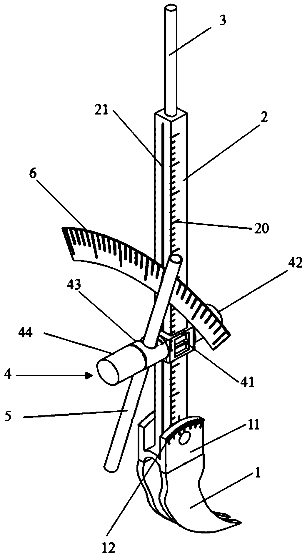
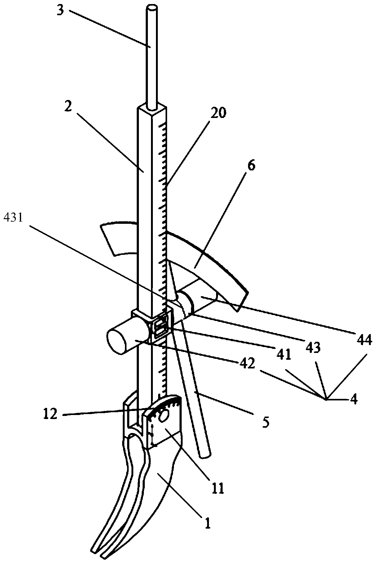
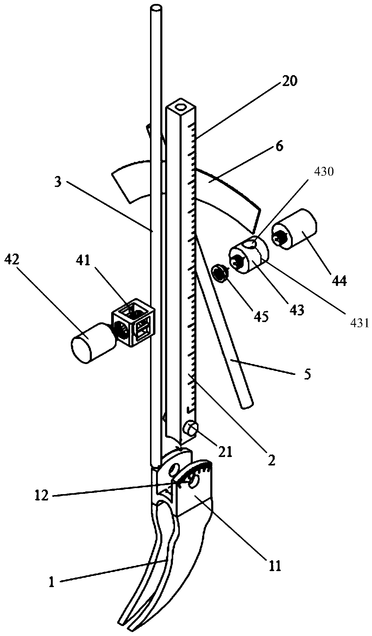
[0022] refer to figure 1 , the positioning device for cortical bone screws in minimally invasive spinal surgery includes a spinous process clip 1, a positioning square tube 2, a Kirschner wire 3, a navigation control device 4, a screw sleeve 5 and an arc protractor 6.

[0023] The spinous process clip 1 includes two spinous process clips, the spinous process clip is an arc-shaped piece with a sharp head end and a wide tail end, the two spinous process clips are parallel to each other and fixedly connected by a transverse piece in the middle, each spinous process clip The rear end of the sheet is provided with a spinous process clip ear 11, and the spinous process clip ear 11 is provided with a perforation, and the two sides of the bottom of the positioning square tube 2 are symmetrically provided with two perfora...

Embodiment 2

[0043] Embodiment 2 provides a method for using a navigation device for cortical bone screws in minimally invasive spinal surgery, using the navigation device for cortical bone screws in minimally invasive spinal surgery provided by Embodiment 1, the method of use includes the following steps :

[0044] Step S1: the spinous process clamp 1 clamps the spinous process on the spine;

[0045] Step S2: Rotate and position the square tube 2 left and right along the pivot 21 until a suitable angle is selected, and determine the rotation angle through the angle marking line 12;

[0046] The method of determining the appropriate angle is as follows: firstly, preoperative CT image analysis is performed; secondly, intraoperative adjustment is carried out according to the analysis results. The included angle between the upper endplate lines and the positioning direction of Kirschner wire 3 will also be fine-tuned through intraoperative lumbar lateral X-ray films.

[0047] Step S3: the Kir...


PUM


Abstract

The invention discloses a navigation device for a cortical bone screw in a minimally invasive spine surgery. The device comprises a spinous process clamp, a positioning square tube, a kirschner wire,a navigation control device, a screw sleeve and an arc protractor, the kirschner wire penetrates through the positioning square tube, the bottom of the kirschner wire penetrates into the spinous process clamp, the navigation control device is slidably arranged on the positioning square tube, the screw sleeve penetrates through the navigation control device, and the arc protractor is arranged at the upper end of the screw sleeve. According to the navigation device for the cortical bone screws in the spine minimally invasive surgery, the positioning square tube, the navigation control device andthe screw sleeve are combined to realize three-dimensional direction adjustment so that the screw-placing accuracy and the screw-placing repeatability are improved, damage to muscle tissue around thespinous process and vertebral isthmus is avoided, assembling and disassembling are convenient, the operation time is shortened, the reusability of the device can be improved, and the operation cost is saved.

Description

technical field [0001] The invention relates to the technical field of medical instruments, in particular to a navigation device for cortical bone screws in minimally invasive spinal surgery. Background technique [0002] When vertebral fractures in patients with osteoporosis need to be reset, and when the stability and fusion rate need to be improved after lumbar decompression and fusion, it is often necessary to add a spinal internal fixation device. The cortical bone screw passes through three layers of cortex to enhance the holding force of the screw and reduce Paravertebral soft tissue exposure. Spinal percutaneous minimally invasive cortical bone screw surgery is to place several positioning needles through a small incision in the middle of the spinous process, and place the screw into the vertebral body without making small incisions on both sides of the spinous process to insert the percutaneous vertebral arch. The root screw avoids the skin incision and subcutaneou...

Claims


Application Information

Patent Timeline
IPC IPC(8): A61B17/90A61B17/70
CPCA61B17/7074A61B17/88A61B17/8897A61B17/90
Inventor 刘玉增张希诺海涌关立刘铁陈彪
Owner BEIJING CHAOYANG HOSPITAL CAPITAL MEDICAL UNIV
Learn More