High-sensitivity immunoassay device and method based on ultrathin optical fiber micro-flow laser
What is Al technical title?
Al technical title is built by PatSnap Al team. It summarizes the technical point description of the patent document.
An immunoassay and high-sensitivity technology, applied in the field of sensing, can solve problems such as difficult to achieve one-time, high-sensitivity immunoassay
Inactive Publication Date: 2020-04-21
UNIV OF ELECTRONICS SCI & TECH OF CHINA
View PDF4 Cites 2 Cited by
Summary
Abstract
Description
Claims
Application Information
AI Technical Summary
This helps you quickly interpret patents by identifying the three key elements:
Problems solved by technology
Method used
Benefits of technology
Problems solved by technology
However, traditional immunoassays are difficult t
Method used
Image
Click on the blue label to locate the original text in one second.
Reading with bidirectional positioning of images and text.
Examples
Embodiment 1
[0035] This embodiment provides a method for measuring the threshold of an ultra-thin fiber microfluidic laser.
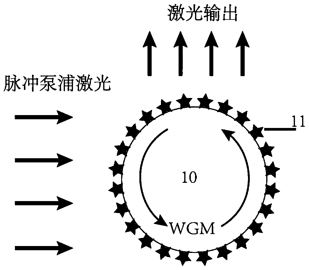
[0036] The structural schematic diagram of the ultra-thin fiber microfluidic laser is as follows figure 2 As shown, a single mode fiber 10 and a streptavidin-cy3 molecule 11 are included. Wherein, the streptavidin-cy3 molecule 11 is fixed on the surface of the single-mode optical fiber 10 through chemical cross-linking and acts as a gain medium. Under the action of the pump light, the light emitted by the gain medium is coupled to the surface of the fiber to form a WGM, and further amplified under the action of the gain medium, finally realizing the laser output.
[0037] The threshold measurement method of the ultra-thin fiber microfluidic laser comprises the following steps:
[0038] Step 1: Fabricate an ultra-thin fiber microfluidic laser.
[0039] First, the optical fiber polymer coating was manually stripped after immersion in acetone for 1 h, and fresh H ...
Embodiment 2
[0048] This implementation is further limited on the basis of Example 1, and provides a detection method for Parkinson's disease biomarker alpha-synuclein based on an ultra-thin fiber microfluidic laser.
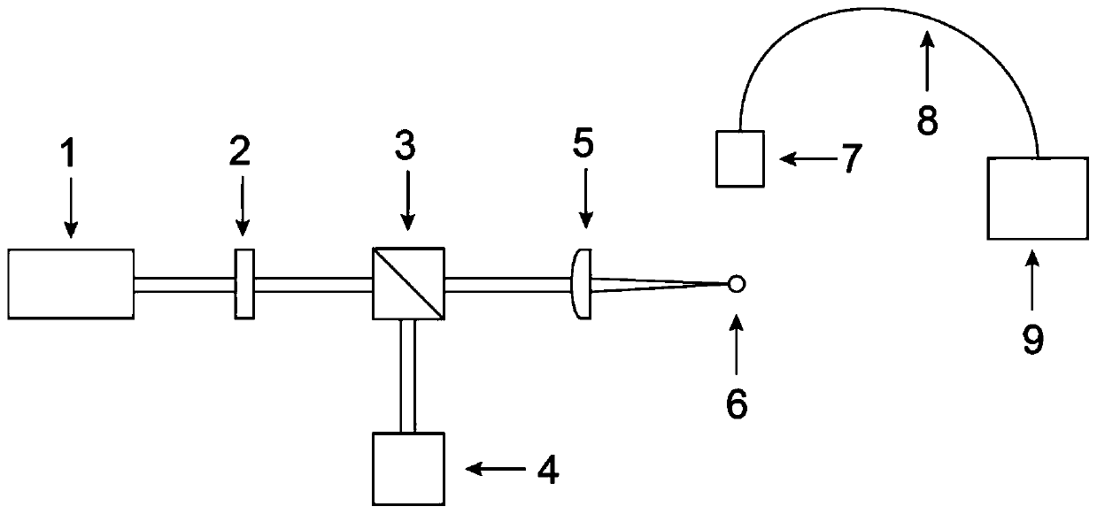
[0049] A high-sensitivity immunoassay device based on an ultra-thin fiber microfluidic laser such as figure 1 As shown, it includes pulse laser 1, attenuation plate 2, beam splitter 3, pulse energy meter 4, cylindrical lens 5, ultra-thin fiber microfluidic laser 6, collection lens 7, collection fiber 8, and spectrum analyzer 9. Among them, the structure diagram of the ultra-thin fiber microfluidic laser is as follows: Figure 5 As shown, it includes a single-mode fiber 10 with a size of 125 μm±0.7 μm, a streptavidin-cy3 molecule 11 , a capture antibody 12 , an antigen 13 and a detection antibody 14 .
[0050] The streptavidin-cy3 molecule 11 and the capture antibody 12 are fixed on the surface of the single-mode optical fiber 10 by means of chemical cross-linking. This par...
PUM
Abstract
The invention discloses a high-sensitivity immunoassay device and a high-sensitivity immunoassay method based on an ultrathin optical fiber micro-flow laser, which belong to the technical field of sensing. The high-sensitivity immunoassay device comprises a pulse laser, an attenuation sheet, a beam splitter, a pulse energy meter, a cylindrical lens, the ultrathin optical fiber micro-flow laser, acollection lens, a collection optical fiber and a spectrum analyzer, wherein the ultra-thin optical fiber micro-flow laser is implemented by crosslinking streptavidin-cy3 molecules on the surface of asingle-mode optical fiber and capturing an antibody; the streptavidin-cy3 molecules are used as a gain medium of the ultra-thin optical fiber micro-flow laser, and the detection of the antigen concentration is realized by means of the antigen and capture antibody. The combination of the antigen and the capture antibody enables the streptavidin-cy3 molecules to be connected to the surface of the optical fiber by means of the detection antibody, and finally, the total streptavidin-cy3 molecules on the surface of the optical fiber are positively correlated with the concentration of the antigen.The surface of the optical fiber supports an echo wall mode and can provide optical feedback for laser generation. High-sensitivity immunoassay of antigen concentration can be realized by detecting laser output of the ultrathin optical fiber micro-flow laser.
Description
technical field [0001] The invention belongs to the field of sensing technology, and in particular relates to a high-sensitivity immune analysis device based on an ultra-thin optical fiber microfluidic laser. Background technique [0002] The immunoassay method uses the antigen-antibody reaction to quantitatively detect the antigen, and has a wide range of applications in the fields of biological detection and disease diagnosis. Traditionally, in immunoassays, the antigen to be tested reacts with the antibody to form an antigen-antibody complex, and the quantitative analysis of the antigen is realized by detecting changes in the fluorescence intensity, absorbance, and electrochemical signal of the reactant. However, traditional immunoassays are difficult to achieve one-time, high-sensitivity immunoassays. [0003] Because the microcavity enhances the interaction between light and matter, the fiber microfluidic laser output signal can sensitively reflect the subtle changes o...
Claims
Application Information
Patent Timeline
Application Date:The date an application was filed.
Publication Date:The date a patent or application was officially published.
First Publication Date:The earliest publication date of a patent with the same application number.
Issue Date:Publication date of the patent grant document.
PCT Entry Date:The Entry date of PCT National Phase.
Estimated Expiry Date:The statutory expiry date of a patent right according to the Patent Law, and it is the longest term of protection that the patent right can achieve without the termination of the patent right due to other reasons(Term extension factor has been taken into account ).
Invalid Date:Actual expiry date is based on effective date or publication date of legal transaction data of invalid patent.