Micro-lens manufacturing method based on CO2 laser melting assisted by high-pressure gas

A high-pressure gas and laser melting technology, which is applied in the direction of lenses, optics, optical components, etc., can solve the problems that ultra-precision machining is difficult to process with micro-lenses, reduce the overall uniformity of micro-lenses, and take a long time for ultra-precision cutting. Avoid mask difficulties, eliminate the limitation of grinding wheel size and wear, and have a large processing range

Active Publication Date: 2020-04-21
北京理工大学重庆创新中心
View PDF3 Cites 0 Cited by
  • Summary
  • Abstract
  • Description
  • Claims
  • Application Information

AI Technical Summary

Problems solved by technology

However, due to the limitation of the size and wear of the grinding wheel, ultra-precision machining is difficult to process micro-lenses of extremely small size
In addition, the ultra-precision

Method used


Image

  • Micro-lens manufacturing method based on CO2 laser melting assisted by high-pressure gas

Examples


Example Embodiment

[0021] Example

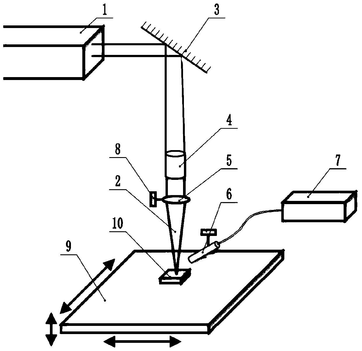
[0022] A high-pressure gas-assisted CO 2 The laser melting microlens manufacturing method is characterized in that, comprises the following steps:

[0023] Step 1: manufacture a preform, and use a machining method to manufacture a preform suitable for the designed microlens structure;

[0024] Step 2: CO 2 Laser 2 Remodeling, Utilizing CO 2 Laser 1 emits CO 2 The laser 2 is reflected to the surface of the preform by the mirror 3, and the CO is made by the laser beam expander 4 and the focusing mirror 5 2 The laser 2 is focused on the surface of the preform to generate a high temperature area, and this temperature is higher than the melting temperature or softening temperature of the material (for example, for quartz materials, a high temperature area above 2000 ° C is generated), and then the nozzle 6 is used to spray high-pressure gas to the softening area. The nozzle 6 is connected to the high-pressure air pump 7 through the trachea, and the reshaped sh...


PUM


Abstract

The invention relates to the technical field of optical material processing equipment, and especially relates to a micro-lens manufacturing method based on CO2 laser melting assisted by a high-pressure gas. The method comprises the following steps of 1, manufacturing a preform, and manufacturing the preform by using a machining method; 2, carrying out CO2 laser reshaping, emitting a CO2 laser to asurface of the preform by using a CO2 laser to generate a high-temperature region at a temperature higher than a melting temperature or softening temperature of a material, and then injecting a high-pressure gas to a softening region by using a nozzle to reshape the preform; and 3, carrying out multi-area remodeling, making a CO2 laser focus and the nozzle keep moving consistently, generating linear motion, spiral motion, rotation motion, sawtooth vibration motion and other relative motion between the CO2 laser focus and the nozzle and an optical material, making the optical material, the CO2laser focus and the nozzle generate relative three-dimensional motion, and carrying out high-temperature melting and shaping on the optical materials in different areas. According to the method, a rapid forming property of laser melting is utilized, high-pressure gas forming is assisted, and efficient machining of an optical material micro lens is achieved.

Description

technical field [0001] The invention relates to the technical field of optical material processing equipment, in particular to a high-pressure gas-assisted CO 2 Microlens Fabrication Method by Laser Melting. Background technique [0002] Optical materials mainly include optical glass materials, quartz materials, optical crystal materials, etc. The optical material microlens structure has the characteristics of small unit size and high degree of integration, which can realize planar / three-dimensional imaging, light interference / diffraction, has functions that cannot be realized by traditional lenses, and can constitute many new optical systems. Microlenses have broad application scenarios in fields such as AR / VR, communication interconnection, and precision guidance. At present, the processing methods of optical material microlens mainly include photolithography, high-energy beam processing, forming replication and ultra-precision machining. [0003] Photolithography is a ...

Claims


Application Information

Patent Timeline
IPC IPC(8): G02B3/00
CPCG02B3/0012G02B3/0018
Inventor 周天丰刘朋官祖伟于谦颜培梁志强刘志兵焦黎解丽静赵文祥王西彬
Owner 北京理工大学重庆创新中心
Why Eureka
Try Eureka