
Heating device for denitration dilution air system

A heating device and air system technology, applied in the field of energy saving and denitrification, can solve the problems of small margin, increased resistance of the flow field disorder system, failure to save energy and reduce consumption, etc., and achieve the effect of solving heating problems

Pending Publication Date: 2020-04-24
CHINA HUADIAN ENG +1
View PDF0 Cites 0 Cited by
  • Summary
  • Abstract
  • Description
  • Claims
  • Application Information

AI Technical Summary

Problems solved by technology

[0004] The denitrification system using urea hydrolysis ammonia production technology as a reducing agent, the product gas needs to be transported with heat (about 160 ° C), when ammonia / air is mixed, hot primary air / secondary air is often used as dilution air, for some renovation projects The boiler hot primary air / secondary air margin is small, and the existing blower needs to be modified, and the hot primary air / secondary air will change with the boiler load; due to the air leakage of the air preheater, the hot primary air Dust in the flue gas will be mixed in the wind / secondary air, and long-term operation will cause blockage or wear of the ammonia injection system pipeline
[0005] Some R&D teams also consider using heat exchangers to heat the dilution air, but there are certain risks in the location and application prospects of the heat exchangers; Wear and corrosion are relatively serious, which is not conducive to long-term safe and stable operation; the heat exchanger is arranged in the SCR outlet flue. After the flue gas passes through the catalyst reaction, the by-product ammonium bisulfate will adhere to the surface of the heat exchanger. The thermal effect is reduced, the resistance of the flow field disorder system increases, and the goal of energy saving and consumption reduction cannot be achieved.

Method used


Image

  • Heating device for denitration dilution air system
  • Heating device for denitration dilution air system
  • Heating device for denitration dilution air system

Examples


Embodiment 1

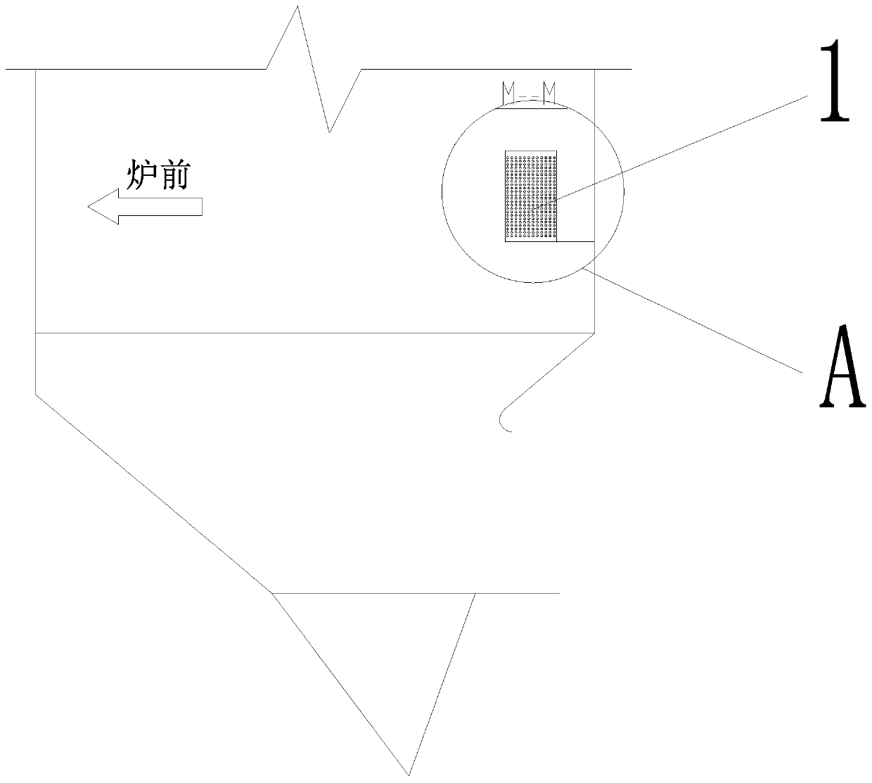
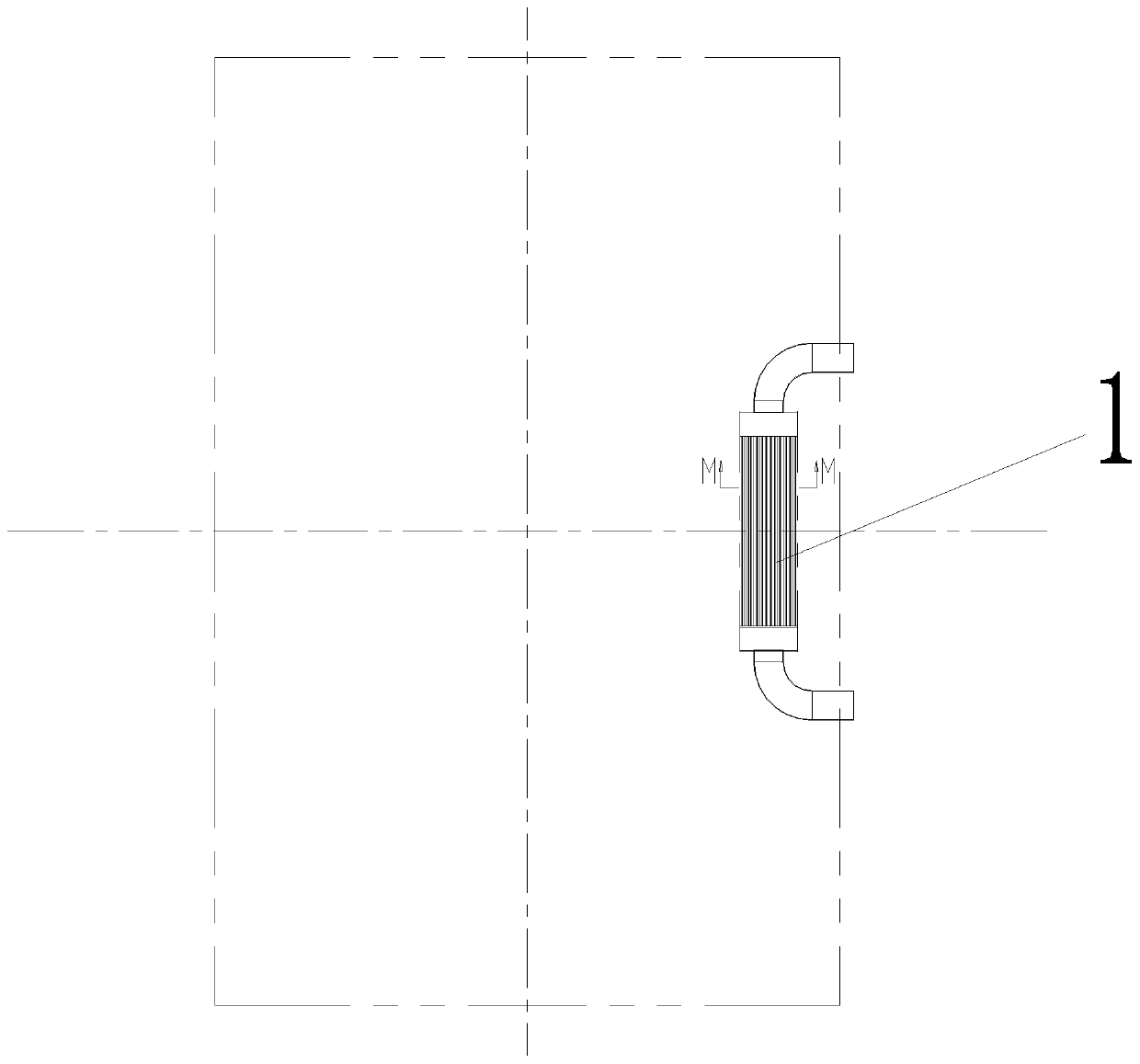
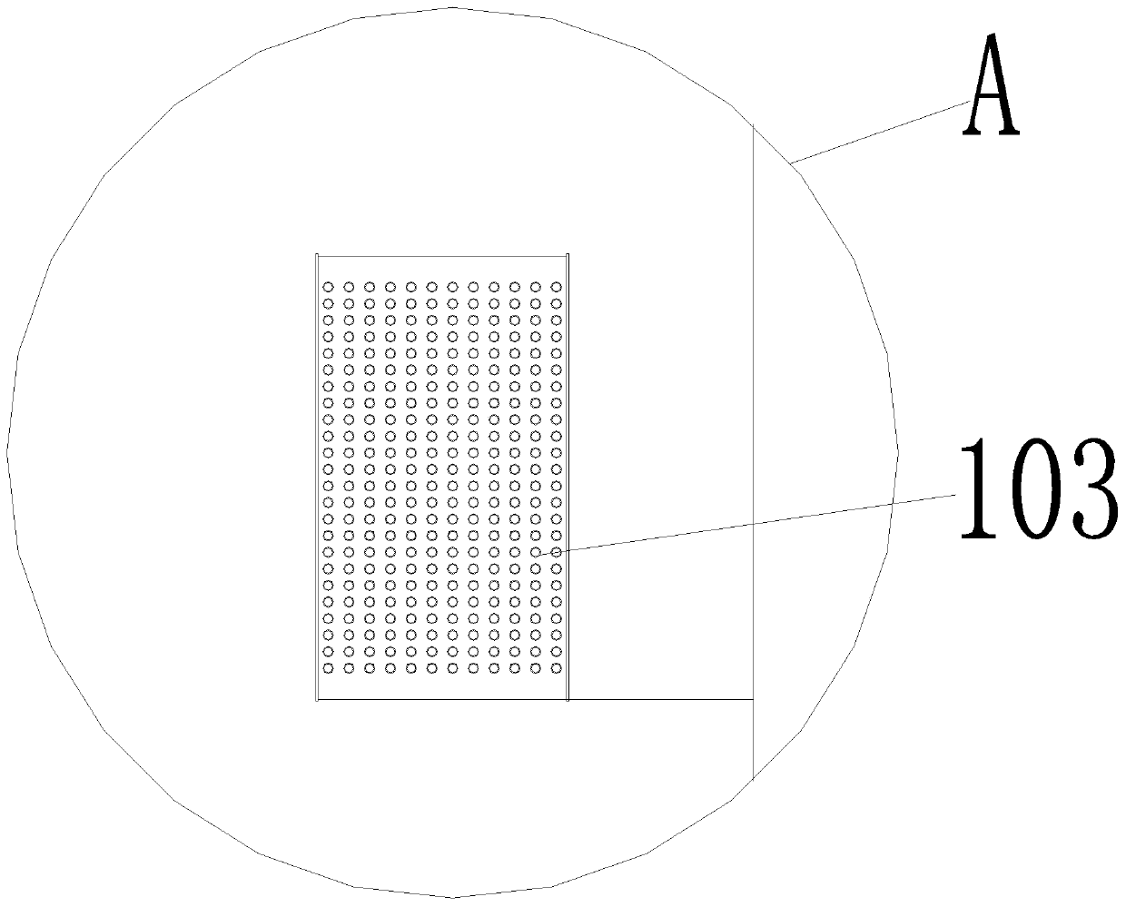
[0031] Embodiment 1 of the present invention: a heating device for denitrification dilution air system, the heating device 1 is installed in the outlet flue 2 of the economizer or in the inlet flue 3 of the low-temperature superheater, and the heating device 1 includes An air duct 101, an air outlet duct 102, and a heat exchange device composed of a plurality of heating branch pipes 103, the plurality of heating branch pipes 103 are arranged between the air inlet pipe 101 and the air outlet pipe 102, and the air inlet pipe 101 and the exchange pipe A first sealing section 104 is provided between the heating devices, a second sealing section 105 is provided between the heat exchange device and the air outlet pipe 102, and one end of the outlet of the heating branch pipe 103 is provided at the economizer outlet flue 2 or The low-temperature superheater enters the flue 3. The heating device 1 is a tube-bundle cross-flow heat exchanger. The heating branch pipe 103 is a W-shaped s...

Embodiment 2

[0032] Embodiment 2 of the present invention: a heating device for denitrification dilution air system, the heating device 1 is installed in the outlet flue 2 of the economizer or in the inlet flue 3 of the low-temperature superheater, and the heating device 1 includes An air duct 101, an air outlet duct 102, and a heat exchange device composed of a plurality of heating branch pipes 103, the plurality of heating branch pipes 103 are arranged between the air inlet pipe 101 and the air outlet pipe 102, and the air inlet pipe 101 and the exchange pipe A first sealing section 104 is provided between the heating devices, a second sealing section 105 is provided between the heat exchange device and the air outlet pipe 102, and one end of the outlet of the heating branch pipe 103 is provided at the economizer outlet flue 2 or The low-temperature superheater enters the flue 3. The heating device 2 is a plate-fin cross-flow heat exchanger. The heating branch pipe 103 is a U-shaped one...

Embodiment 3

[0033] Embodiment 3 of the present invention: a heating device for denitrification dilution air system, the heating device 1 is installed in the outlet flue 2 of the economizer or in the inlet flue 3 of the low-temperature superheater, and the heating device 1 includes An air duct 101, an air outlet duct 102, and a heat exchange device composed of a plurality of heating branch pipes 103, the plurality of heating branch pipes 103 are arranged between the air inlet pipe 101 and the air outlet pipe 102, and the air inlet pipe 101 and the exchange pipe A first sealing section 104 is provided between the heating devices, a second sealing section 105 is provided between the heat exchange device and the air outlet pipe 102, and one end of the outlet of the heating branch pipe 103 is provided at the economizer outlet flue 2 or The low-temperature superheater enters the flue 3. The heating device 1 is a tube-bundle cross-flow heat exchanger. The heating branch pipe 103 is an L-shaped ...


PUM


Abstract

The invention discloses a heating device for a denitration dilution air system. The heating device is installed in an outlet flue of a coal economizer or an inlet flue of a low-temperature superheater, the heating device comprises a plurality of branch pipes, the outlet ends of the branch pipes are arranged in the outlet flue of the coal economizer or the inlet flue of the low-temperature superheater, and the heating device comprises heating branch pipes. The heating device used for heating dilution air is arranged in the outlet flue of the coal economizer or the inlet flue of the low-temperature superheater, and heat of high-temperature flue gas serves as a heating source, so long-term safe and stable operation can be facilitated, the problems of dust accumulation, blockage and the like do not exist, and the heating problem of denitration dilution air can be effectively solved.

Description

technical field [0001] The invention relates to a heating device for a denitrification dilution air system, which belongs to the technical field of denitrification and energy saving. Background technique [0002] SCR (Selective Catalytic Reduction) technology is currently the most advanced, mature and reliable flue gas denitrification technology in the field of boiler nitrogen oxide removal technology in China. NH 3 AS with NO X The basic reduction reactant of the reaction directly affects the selection of the denitrification process route, among which the technology of using liquid ammonia and urea as the reducing agent has been widely used. DL / T 5480-2013 of "Technical Regulations for Flue Gas Denitration Design of Thermal Power Plants" clearly stipulates that "the ammonia gas concentration at the outlet of the ammonia / air mixer in the auxiliary system shall not exceed 5% (volume fraction)", therefore, reasonable control of dilution Air volume is critical. [0003] The...

Claims


Application Information

Patent Timeline
IPC IPC(8): B01D53/86B01D53/56F28D21/00
CPCB01D53/8631B01D2251/2062B01D2258/0283F28D21/0014
Inventor 孙立群
Owner CHINA HUADIAN ENG
Learn More