
A kind of manufacturing process of metal film screen plate

A manufacturing process and metal film technology, which is applied in the field of metal film screen plate manufacturing process, can solve the problems of undisclosed process details and methods, and achieve the effects of flexible bonding, high production efficiency, and high bonding strength

Active Publication Date: 2022-01-04
ZHEJIANG SHUOKE SCI & TECH
View PDF13 Cites 0 Cited by
  • Summary
  • Abstract
  • Description
  • Claims
  • Application Information

AI Technical Summary

Problems solved by technology

However, the specific process details and methods to realize the production of precision stencils are not disclosed;

Method used


Image

  • A kind of manufacturing process of metal film screen plate
  • A kind of manufacturing process of metal film screen plate
  • A kind of manufacturing process of metal film screen plate

Examples


Embodiment 1

[0036] see figure 1 As shown, in the manufacturing process of a metal film screen involved in this embodiment, the metal film 101 is fixed on the transfer film 102, and then the glue that plays the adhesive function after heating is attached to the metal film 101 -103, through laser engraving, remove excess metal film-101 and glue-103 (that is, gap-104) to achieve the desired shape, and combine with the screen by hot pressing.

Embodiment 2

[0038] see figure 2 As shown, in the manufacturing process of a metal film screen involved in this embodiment, the metal film 201 is fixed on the transfer film 202, and the redundant metal film 201 is removed by laser engraving or electroforming (ie Gap 2 204), to reach the desired shape, and then attach the glue 2 203 that has been heated to play an adhesive function on the metal film 2 201, and remove the excess glue 2 (that is, the gap 3 205) by laser engraving to achieve the same The metal film 2 201 forms the same structure, and then combined with the screen by hot pressing.

[0039] In this solution, the metal film 201 and the glue 203 are cut separately, so that the metal film 201 can be electroformed, and the glue 203 can be laser engraved, so that the requirements for the laser are reduced. Among them, electroforming can also be replaced by etching operation.

Embodiment 3

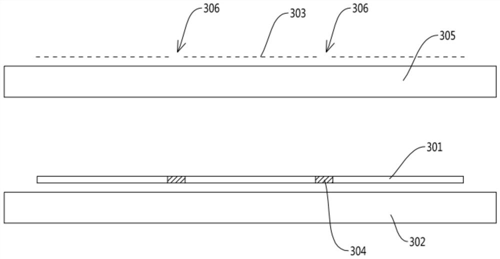
[0041] see image 3 with Figure 4 As shown, in the manufacturing process of a metal film screen involved in this embodiment, the metal film 301 is fixed on the transfer film 302, and the redundant metal film 301 is removed by laser engraving or electroforming (ie Gap 4 304) reaches the desired shape; meanwhile, glue 3 303 is fixed on the transfer film 4 305, and excess glue 3 303 (that is, gap 5 306) is removed by laser engraving to form with the metal film 3 301 With the same structure, first hot press the glue three 303 onto the metal film three 301, and then heat press the metal film three 301 to the screen through the glue three 303.

[0042] In this solution, the metal film 301 and the glue 303 are cut separately, so that the metal film 301 can be electroformed, and the glue 303 can be engraved by laser, so that the requirements for the laser are reduced. Among them, electroforming can also be replaced by etching operation.

[0043]The manufacturing process of the met...


PUM

PropertyMeasurementUnit
thicknessaaaaaaaaaa

Abstract

The invention discloses a manufacturing process of a metal film screen plate. The manufacturing process of the metal film screen plate includes taking the screen in advance and laying it flat, and then placing the metal film on the transfer film, and attaching the metal film to the metal film after heating. The glue that plays the role of adhesion, and finally heat-press the side of the metal film attached to the glue to the screen, and remove the transfer film; wherein, before the hot-pressing operation, the metal film is engraved to achieve the desired shape. The metal film screen plate is bonded to the screen screen plate by glue to make a printing screen plate, and the metal film screen plate can be produced quickly and efficiently by adopting the process method provided by the invention. The metal film screen plate is resistant to the extrusion of foreign particles during use, and is not easy to wear and tear. It can improve printing stability and production efficiency, reduce printing costs, and has perfect overall functions and strong practicability.

Description

technical field [0001] The invention relates to the technical field of screen printing, more specifically, it relates to a manufacturing process of a metal film screen. Background technique [0002] As a template that can quickly print and reproduce patterns, the printing screen is widely used in many industries such as circuit boards, microelectronics, lenses, light guide plates, touch screens, and solar cells. The traditional printing template manufacturing process is photosensitive emulsion direct plate-making method. The specific method is: stretch polyester screen or stainless steel wire mesh to a certain tension, and fix it on a special frame; then coat photosensitive glue on the surface of the screen, pass The exposure method reproduces the graphics to be printed. The prepared printing template is mainly composed of screen and photosensitive adhesive film. As a kind of resin polymer, the photosensitive adhesive film is weak in strength. It is easy to be worn out duri...

Claims


Application Information

Patent Timeline
Patent Type & Authority Patents(China)
IPC IPC(8): B41C1/14
CPCB41C1/145
Inventor 章征国章征强蒋豪跃
Owner ZHEJIANG SHUOKE SCI & TECH
Learn More