Composite biological filter material for biological aerated filter

A technology of aerated biological filter and biological filter material, which is applied in sustainable biological treatment, biological water/sewage treatment, water/sludge/sewage treatment, etc. Efficiency and other issues, to achieve the effect of extending the contact time, high water treatment efficiency, and increasing the contact area

Active Publication Date: 2020-04-28
NANJING GONGCHENG RES INST OF ENERGY CONSERVATION & NEW MATERIALS TECH CO LTD
View PDF26 Cites 0 Cited by
  • Summary
  • Abstract
  • Description
  • Claims
  • Application Information

AI Technical Summary

Problems solved by technology

[0003] Patent 201710520888 .5 discloses a biological aerated filter, which discloses a biological filler, and the biological filler (4) is filled between the primary filter plate (2) and the secondary filter plate (3), The primary filter plate (2) is filled with small particle filter material (5), and the small particle filter material (5) is granular activated carbon, volcanic filter stone, ceramsite or slag, and the technical problem to be solved is to provide a microbial It is a biological filter material with sufficient and uniform contact with sewage, high treatment efficiency and microbial utilization rate, but it uses a biological filter material with fine particles. The problem with the biological filter material with fine particles is that the particles are small and the particles are arranged tightly. Solid, thereby reducing the gap between particles, will reduce the amount of film hanging, thereby reducing the efficiency of sewage treatment

Method used


Image

  • Composite biological filter material for biological aerated filter
  • Composite biological filter material for biological aerated filter

Examples


Embodiment Construction

[0022] The present invention is described in further detail now in conjunction with accompanying drawing. These drawings are all simplified schematic diagrams, which only illustrate the basic structure of the present invention in a schematic manner, so they only show the configurations related to the present invention.

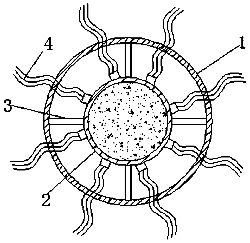
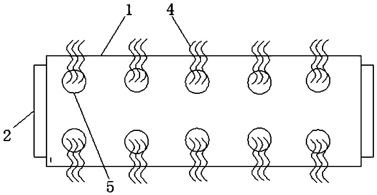
[0023] see figure 1 and figure 2 , a composite biological filter material for biological aerated filter, including an outer cylinder 1 and an inner cylinder 2, the outer cylinder 1 and the inner cylinder 2 are connected by a connecting rod 3, the outer cylinder 1 and the inner cylinder 2 There are several outer through holes 5 and inner through holes respectively on the inner cylinder body 2, the positions of the outer through holes 5 on the outer cylinder body 1 and the inner through holes on the inner cylinder body 2 are in one-to-one correspondence, the outer through holes 5 and the inner through holes A fiber filter material 4 is arranged between the in...


PUM


Abstract

The invention relates to the technical field of biological filter materials, in particular to a composite biological filter material for a biological aerated filter. The equipment comprises an outer cylinder body and an inner cylinder body, the outer cylinder body and the inner cylinder body are connected through a connecting rod; a plurality of outer through holes and a plurality of inner throughholes are respectively formed in the outer cylinder body and the inner cylinder body; the positions of the outer through holes in the outer cylinder body are in one-to-one correspondence with those of the inner through holes in the inner cylinder body; a fiber filter material is arranged between the outer through hole and the inner through hole, the fiber filter material is fixed in the inner through hole and penetrates through the outer cylinder body through the outer through hole, vermiculite and ceramsite are arranged in the inner cylinder body, baffle plates are arranged at the two ends of the inner cylinder body, and a plurality of water inlet holes or water outlet holes are formed in the two baffle plates respectively; the vermiculite, the ceramsite and the fiber filter material areused as the filter materials, and the vermiculite and the ceramsite are placed in the inner cylinder, so that the contact time of sewage and the vermiculite and the ceramsite is prolonged, the contact area of the sewage and the vermiculite and the ceramsite is increased, and the water treatment efficiency is higher.

Description

technical field [0001] The invention relates to the technical field of biological filter materials, in particular to a composite biological filter material used in aerated biological filter tanks. Background technique [0002] In the biological aerated filter, the sewage passes through the filter material layer, and the pollutants contained in the water body are intercepted by the filter material layer, and are transformed by the biodegradation attached to the filter material. At the same time, the dissolved organic matter and specific substances are also removed, and the produced The sludge remains in the filter layer, and only the purified water passes through, so that a complete biological treatment can be achieved in a closed reactor without the need for a secondary settling tank downstream for sludge settlement. [0003] Patent 201710520888 .5 discloses a biological aerated filter, which discloses a biological filler, and the biological filler (4) is filled between the ...

Claims


Application Information

Patent Timeline
Patent Type & Authority Applications(China)
IPC IPC(8): C02F3/10
CPCC02F3/10C02F3/106C02F3/107Y02W10/10
Inventor 刘东孙俊杰邹丹卢俊
Owner NANJING GONGCHENG RES INST OF ENERGY CONSERVATION & NEW MATERIALS TECH CO LTD
Why Eureka
Try Eureka