Ceramic slurry, ceramic diaphragm and lithium ion battery

A technology of ceramic slurry and ceramic diaphragm, which is applied in the direction of secondary batteries, battery pack components, circuits, etc., can solve the problems that the trend of diaphragm thinning is contradictory, the anti-lithium dendrite puncture ability has not been greatly improved, and needs to be improved. , to achieve good anti-lithium dendrite puncture performance, excellent electronic barrier properties, and excellent anti-lithium dendrite puncture performance

Active Publication Date: 2020-04-28
乐凯胶片股份有限公司
View PDF8 Cites 2 Cited by
  • Summary
  • Abstract
  • Description
  • Claims
  • Application Information

AI Technical Summary

Problems solved by technology

However, the application of a thicker ceramic coating will inevitably lead to an increase in the overall thickness and surface density of the separator, which is contrary to the trend of thinning the separator; The anti-lithium dendrite puncture ability of the lithium battery separator has not been greatly improved
[0004] Thereby, the relevant technology of existing lithium-ion battery still needs to be improved

Method used


Image

  • Ceramic slurry, ceramic diaphragm and lithium ion battery
  • Ceramic slurry, ceramic diaphragm and lithium ion battery
  • Ceramic slurry, ceramic diaphragm and lithium ion battery

Examples


Embodiment 1

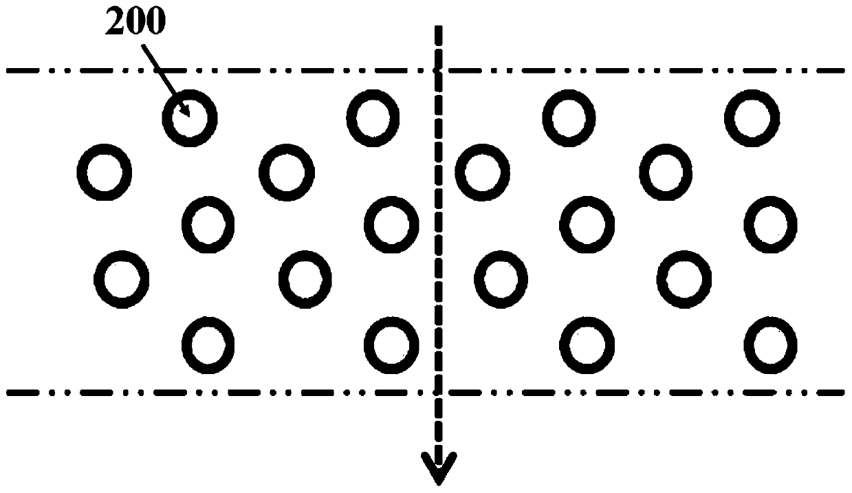
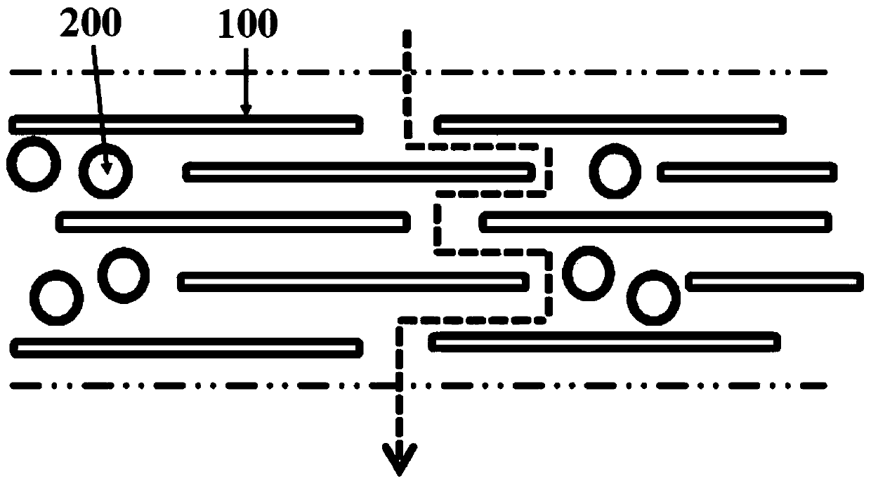
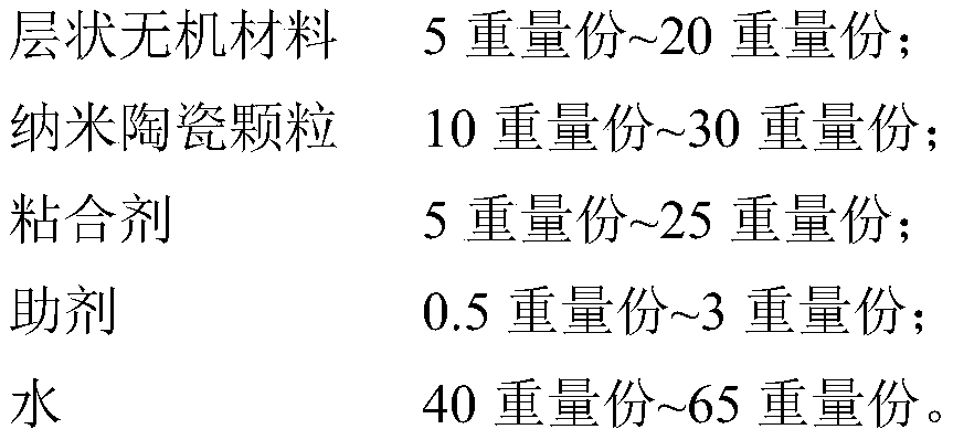
[0054] 15g of montmorillonite, 25g of nano-ceramic particles, 5g of polymethyl methacrylate and 2.5g of fatty alcohol polyoxyethylene ether were evenly dispersed into 52.5g of water under stirring, and a ceramic slurry was prepared by sand milling, wherein the montmorillonite The diameter-thickness ratio of the soil is 200-350, and the specific surface area is 240m 2 / g, the average wafer thickness is less than 25nm. A polyethylene film with a thickness of 5 μm prepared by Lucky Film Co., Ltd. was used as the base film. After the ceramic slurry is prepared, the prepared ceramic slurry is evenly coated on one surface of the base film with a wire rod, and then dried in an oven at 70°C to evaporate the water to obtain a ceramic with a ceramic coating thickness of 3 μm. diaphragm.

Embodiment 2

[0056] Disperse 10g of montmorillonite, 30g of nano-ceramic particles, 8g of polymethyl methacrylate and 2g of fatty alcohol polyoxyethylene ether into 50g of water evenly under stirring, and prepare a ceramic slurry through sand milling, wherein the hydrotalcite powder The ratio of diameter to thickness is 350-400, and the specific surface area is 550m 2 / g, the average wafer thickness is less than 25nm. A polyethylene film with a thickness of 7 μm prepared by Lucky Film Co., Ltd. was used as the base film. After preparing the ceramic slurry, the prepared ceramic slurry was evenly coated on one surface of the base film with a wire rod, and then dried in an oven at 70°C to evaporate the water to obtain a ceramic coating with a thickness of 2.5 μm. Ceramic diaphragm.

Embodiment 3

[0058] 5g of montmorillonite, 35g of nano-ceramic particles, 3g of polymethyl methacrylate and 0.5g of fatty alcohol polyoxyethylene ether were uniformly dispersed into 50g of water under stirring, and prepared into a ceramic slurry by sand milling, wherein the montmorillonite The diameter-thickness ratio is 150-200, and the specific surface area is 150m 2 / g, the average wafer thickness is less than 25nm. A polyethylene film with a thickness of 16 μm prepared by Lucky Film Co., Ltd. was used as the base film. After the ceramic slurry is prepared, the prepared ceramic slurry is evenly coated on one surface of the base film with a wire rod, and then dried in an oven at 70°C to evaporate the water to obtain a ceramic with a ceramic coating thickness of 2 μm. diaphragm.


PUM

PropertyMeasurementUnit
Thicknessaaaaaaaaaa
Thicknessaaaaaaaaaa
Thicknessaaaaaaaaaa

Abstract

The invention provides ceramic slurry, a ceramic diaphragm and a lithium ion battery. The ceramic slurry includes: a layered inorganic material; nano ceramic particles; a binder; an auxiliary agent; and water. The ratio of the radius to the thickness of the layered inorganic material is 150-400. The ceramic slurry is strong in stability, can meet the actual production requirements, and can prolongthe growth path of lithium dendrites in the lithium ion battery, so that the lithium dendrites puncture resistance of the ceramic diaphragm is good; meanwhile, the ceramic coating formed by the ceramic slurry can enable the thermal shrinkage degree of the ceramic diaphragm to be small and the stability to be good.

Description

technical field [0001] The invention relates to the technical field of lithium-ion battery diaphragms, and in particular, relates to ceramic slurry, ceramic diaphragms and lithium-ion batteries. Background technique [0002] At present, with the increasing problems of environmental pollution and energy shortage, lithium-ion batteries with advantages such as high energy density, long cycle life, high power density, and no memory effect are increasingly recognized internationally and widely used in digital electronic products. , new energy vehicles and many other fields. As one of the key inner components that isolate the positive and negative electrodes of the battery to prevent short circuits and conduct lithium ions, the performance of the separator determines the interface structure, internal resistance, etc. of the battery, and affects the capacity and cycle life of the battery. Especially the safety performance of the battery. However, separators made of traditional po...

Claims


Application Information

Patent Timeline
IPC IPC(8): C04B26/18H01M2/14H01M2/16H01M10/0525C04B40/02C04B111/90C04B111/94H01M50/434H01M50/449H01M50/491
CPCC04B26/18H01M10/0525C04B2111/00844C04B2111/90C04B2111/94H01M50/403H01M50/431H01M50/411C04B14/104C04B18/023C04B24/32C04B40/0263C04B22/06Y02E60/10
Inventor 张文静王莉吴斌章峰勇王小记柳青
Owner 乐凯胶片股份有限公司
Why Eureka
Try Eureka