Method for directly reducing materials by using rotary hearth furnace

A rotary hearth furnace and material technology, which is used in rotary drum furnaces, furnaces, furnace types, etc., can solve the problems of powder materials must be agglomerated, high calorific value gas dependence, etc., and achieve the effect of increasing the charging amount

Active Publication Date: 2020-04-28
CENT IRON & STEEL RES INST +1
View PDF10 Cites 2 Cited by
  • Summary
  • Abstract
  • Description
  • Claims
  • Application Information

AI Technical Summary

Problems solved by technology

[0005] In view of the above analysis, the embodiment of the present invention aims to provide a method for directly reducing materials using a rotary hearth furnace to solve the problem that the powdery materials must be agglomerated when the existing rotary hearth furnace is reduced and the existing rotary hearth furnace has a high calorific value. Technical issues of gas dependence

Method used


Image

  • Method for directly reducing materials by using rotary hearth furnace
  • Method for directly reducing materials by using rotary hearth furnace
  • Method for directly reducing materials by using rotary hearth furnace

Examples


Embodiment 1

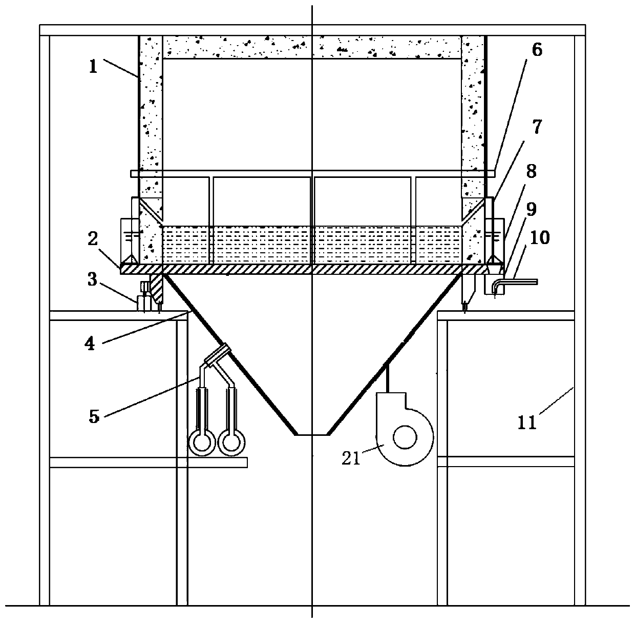
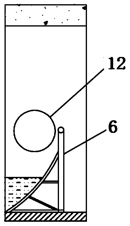
[0042] This embodiment discloses a rotary hearth furnace, such as figure 1 , figure 2 , Figure 4~6 As shown, it includes a rotary hearth furnace body 19, a water seal unit and an air supply unit. The rotary furnace body includes an annular fixed furnace body and an annular rotating furnace bottom 2 located below the annular fixed furnace body 1. The annular fixed furnace body 1 and the annular The rotating furnace bottom 2 is sealed by a water seal unit; the bottom end of the annular rotating furnace bottom 2 is a bottom plate with holes on which the mixture is laid. The unit rotates with the annular rotating furnace bottom 2 .

[0043] Specifically, the rotary hearth furnace includes a rotary hearth furnace body 19, a water seal unit and an air supply unit. The rotary hearth furnace body 19 includes an annular fixed furnace body 1 and an annular rotating hearth 2, and the annular rotating hearth 2 is arranged on an annular fixed furnace body. Directly below the furnace b...

Embodiment 2

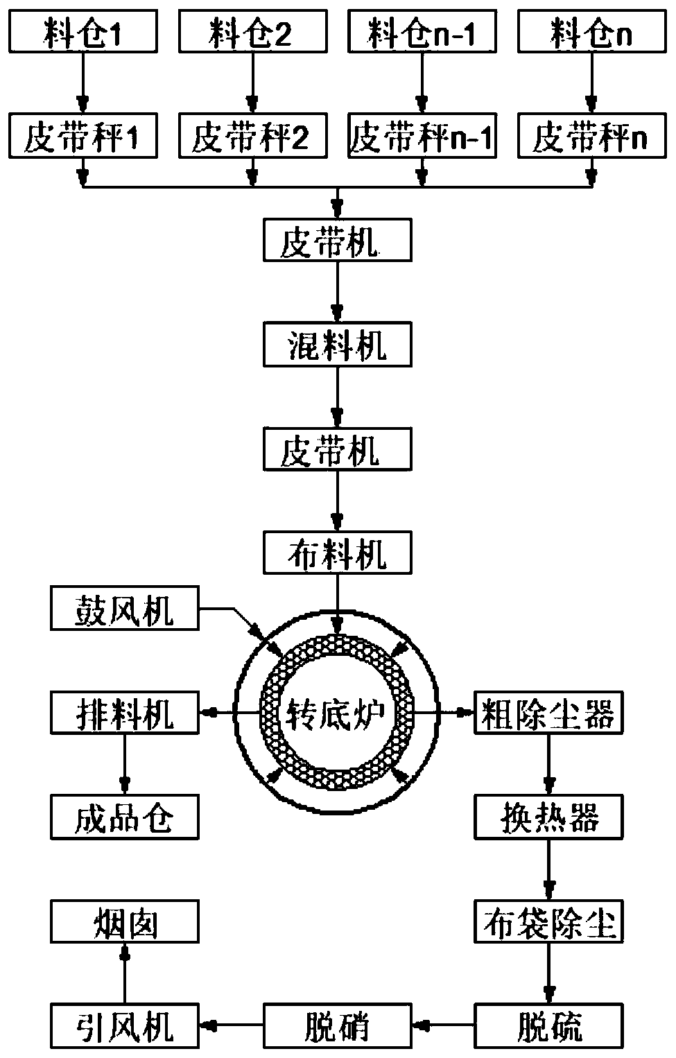
[0073] This embodiment provides a method of direct reduction using a rotary hearth furnace, using the rotary hearth furnace in Example 1, such as image 3 As shown, when the air distribution wind box 4 is connected with the blower, the method for utilizing the rotary hearth furnace for direct reduction comprises the following steps:

[0074] Step 1. Load various materials in silo 1 to silo n, weigh and feed them to belt conveyor P through belt scale 1 to belt scale n, and transport them to the mixer through belt conveyor P for mixing and mixing. The final mixture is transported to the conical roller distributor 18 of the rotary hearth furnace by the belt conveyor S, and is evenly distributed to the hearth of the rotary hearth furnace by the conical roller distributor 18;

[0075] Step 2, the combustion-supporting gas enters the mixture layer through the annular air distribution pipe 13, the air distribution bellows 4 and the first hole, and simultaneously the gas enters the mi...


PUM


Abstract

The invention relates to a method for directly reducing materials by using a rotary hearth furnace, and belongs to the technical field of direct reduction by using the rotary hearth furnace. The method for directly reducing the materials by using the rotary hearth furnace solves the problems that the powdery materials have to be agglomerated when existing rotary hearth furnaces are used for reduction and the existing rotary hearth furnaces depend on gas with a high heating value. The method includes the following steps that step 1, the various materials loaded into silos are mixed to form a mixture, and the mixture is conveyed to a bottom plate of a ring-shaped rotating furnace bottom; step 2, combustion-supporting gas is supplied to the bottom plate of the ring-shaped rotary hearth furnace through an air supply unit; step 3, after an air blower is ignited, as the ring-shaped rotating furnace bottom rotates one circle, the mixture on the bottom plate undergoes physical and chemical reactions, and the roasted mixture is discharged from the rotary hearth furnace through a material shoveling device and a spiral discharger. According to the method for directly reducing the materials byusing the rotary hearth furnace, the reduction of the powdery materials directly into the furnace is realized and the rotary hearth furnaces get rid of the dependence on the gas with the high heatingvalue.

Description

technical field [0001] The invention relates to the technical field of direct reduction by using a rotary hearth furnace, in particular to a method for directly reducing materials by using a rotary hearth furnace. Background technique [0002] There are a large number of iron-containing solid wastes such as non-ferrous smelting and chemical waste residues and red mud piled up for a long time in China. Due to the high amount of harmful elements, it is difficult to use them. Rotary hearth furnace technology is very suitable for the treatment and utilization of these iron-containing solid wastes. [0003] At present, the problems existing in foreign rotary hearth furnaces are as follows: [0004] First of all, in terms of the choice of heating fuel, most of the domestic and foreign industrialized rotary hearth furnaces currently use natural gas or high calorific value gas. The investment and maintenance cost of equipment is large, and it pollutes the environment. When the cal...

Claims


Application Information

Patent Timeline
Patent Type & Authority Applications(China)
IPC IPC(8): C21B13/08C22B19/38
CPCC21B13/0066C21B13/08C22B19/38
Inventor 王锋张俊高建军万新宇严定鎏周和敏齐渊洪
Owner CENT IRON & STEEL RES INST
Why Eureka
Try Eureka