
High-low pressure double-working-medium ORC power generation system with regenerative cycle

A power generation system, high and low voltage technology, applied in the field of ORC power generation system, can solve the problems of energy saving and environmental protection performance to be improved, and achieve the effect of improving waste heat recovery method, reducing heat load and reducing pollution

Active Publication Date: 2020-04-28
BEIJING INSTITUTE OF PETROCHEMICAL TECHNOLOGY
View PDF17 Cites 3 Cited by
  • Summary
  • Abstract
  • Description
  • Claims
  • Application Information

AI Technical Summary

Problems solved by technology

[0004] The energy saving and environmental protection performance of the ORC power generation system in the prior art still needs to be improved

Method used


Image

  • High-low pressure double-working-medium ORC power generation system with regenerative cycle

Examples


specific Embodiment approach

[0016] The preferred embodiment of the high-low pressure duplex ORC power generation system with heat recovery cycle of the present invention is:

[0017] Including heat source system, cold source system, high-voltage cycle power generation system, low-voltage cycle power generation system;

[0018] The high-pressure cycle power generation system includes a high-pressure evaporator and a liquid separator connected to each other. The gas-phase outlet of the liquid separator enters the expander, and the liquid-phase outlet flows into the liquid collector; the exhaust gas outlet of the expander The working fluid enters the liquid collector after being directly condensed by the condenser, and the working medium at the outlet of the extraction steam enters the liquid collector through the extraction steam regenerator and the exhaust steam regenerator; After the regenerator and extraction steam regenerator are preheated, they return to the high-pressure evaporator through the booste...

specific Embodiment

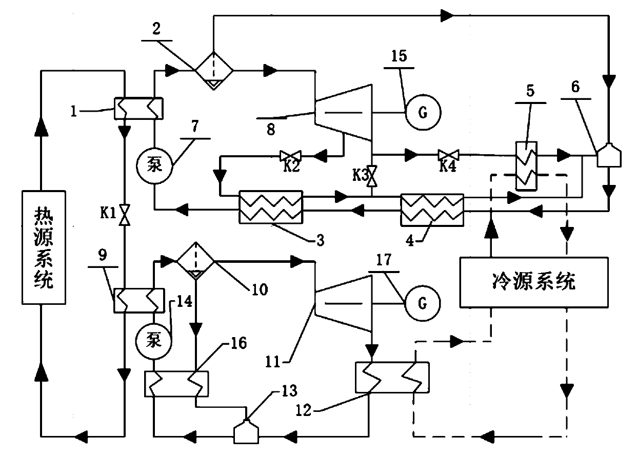
[0049] Such as figure 1 shown. The system includes a high-voltage cycle power generation system, a low-voltage cycle power generation system, a cold source system, and a heat source system; the high-voltage power generation cycle system recycles high-grade heat from the heat source system, and the remaining low-grade heat is recycled by low-pressure cycle. The cold source system is responsible for providing the cold energy required by the two cycles, and the heat source system provides the heat of the entire system.

[0050] As a preferred example of the present invention, the high-pressure cycle includes a liquid separator 2, an expander 8, an extraction steam regenerator 3, an exhaust steam regenerator 4, a condenser 5, and a liquid collector connected in sequence to form a closed cycle. 6, booster pump 7; the high-pressure cycle power generation system exchanges heat with the heat source through the high-pressure evaporator 1; the extraction steam and exhaust steam of the ex...


PUM


Abstract

The invention discloses a high-low-pressure double-working-medium ORC power generation system with regenerative cycle. The system comprises a high-pressure cycle power generation system, a low-pressure cycle power generation system, a cold source system and a heat source system. The high-pressure cycle power generation system and the low-pressure cycle power generation system adopt different working media to carry out gradient recovery on heat of different grades of the heat source system; on the basis that a steam extraction heat regenerator and an exhaust steam heat regenerator are arranged,the high-pressure cycle power generation system is further provided with a bypass loop so as to ensure safe operation of the unit; and the cold source system provides cooling capacity required by condensation for condensers of the high-pressure cycle power generation system and the low-pressure cycle power generation system. According to the system, on the basis of existing ORC cycle, a traditional waste heat recovery method is improved, waste heat is recovered in a stepped mode through the high-low pressure double-working-medium ORC power generation system with the regenerative cycle, the heat load of an evaporator is reduced, and the heat efficiency of the ORC power generation system is effectively improved.

Description

technical field [0001] The invention relates to an ORC power generation system in the field of energy utilization, in particular to a high-low pressure duplex ORC power generation system with a heat recovery cycle. Background technique [0002] With the continuous development of global society and economy, the demand for energy continues to increase. At the same time, problems such as environmental pollution and global warming have put enormous pressure on environmental protection and governance, and the world is also facing an energy crisis brought about by the depletion of fossil energy. Therefore, in the field of energy utilization, improving energy utilization has become an important means to alleviate the global energy shortage. [0003] Organic Rankine cycle (ORC) is a Rankine cycle with low-boiling point organic matter as the circulating working medium. It is a key technology in the field of waste heat utilization. After the organic working medium is pressurized and ...

Claims


Application Information

Patent Timeline
IPC IPC(8): F01K13/00F01K17/06F01K23/02F01K11/02F01K25/10F01D15/10
CPCF01K13/00F01K17/06F01K23/02F01K11/02F01K25/10F01D15/10Y02P80/15
Inventor 刘远超钟建斌邵钶王子铭
Owner BEIJING INSTITUTE OF PETROCHEMICAL TECHNOLOGY
Learn More