Slurry removing method and assembly and system for implementing method

A slurry and component technology, which is applied in the field of systems, slurry removal methods and components to realize the method, can solve the problems of destroying the current collector, reducing the safety performance of the battery cell, operating efficiency, and operating stability to be improved. The effect of simple process, excellent safety performance and low cost

Pending Publication Date: 2020-04-28
HUIZHOU LIWINON NEW ENERGY TECH CO LTD
View PDF0 Cites 3 Cited by
  • Summary
  • Abstract
  • Description
  • Claims
  • Application Information

AI Technical Summary

Problems solved by technology

[0004] At present, the industry generally adopts the method of scraping off part of the active material layer after coating and drying. However, since the pole piece has been dried, the active material layer and the current collector have been dried, and then scraping off part of the active material layer will damage the current collector and reduce the The safety performance of the battery is improved, and the operating efficiency and operating stability still need to be improved

Method used


Image

  • Slurry removing method and assembly and system for implementing method
  • Slurry removing method and assembly and system for implementing method

Examples


Embodiment 1

[0029] This embodiment provides a slurry removal method, comprising the following steps:

[0030] Step 1, setting a preliminary empty foil area 31 on the surface of the current collector 1, and coating the slurry on the current collector 1 to obtain the active material layer 3;

[0031] Step 2, setting the upper part of the preparatory empty foil area 31 as a positive pressure, so that the slurry on the surface of the preparatory empty foil area 31 is gathered;

[0032] Step 3: Set the upper part of the preparatory empty foil area 31 as a negative pressure, and suck the slurry accumulated on the surface of the preparatory empty foil area 31 to obtain the empty foil area 32 .

[0033] Further, setting the upper part of the preparatory empty foil area 31 as a positive pressure is specifically to pass compressed air to the preparatory empty foil area 31 . Pass compressed air above the preparatory empty foil area 31, so that the compressed air forms a positive pressure air knife,...

Embodiment 2

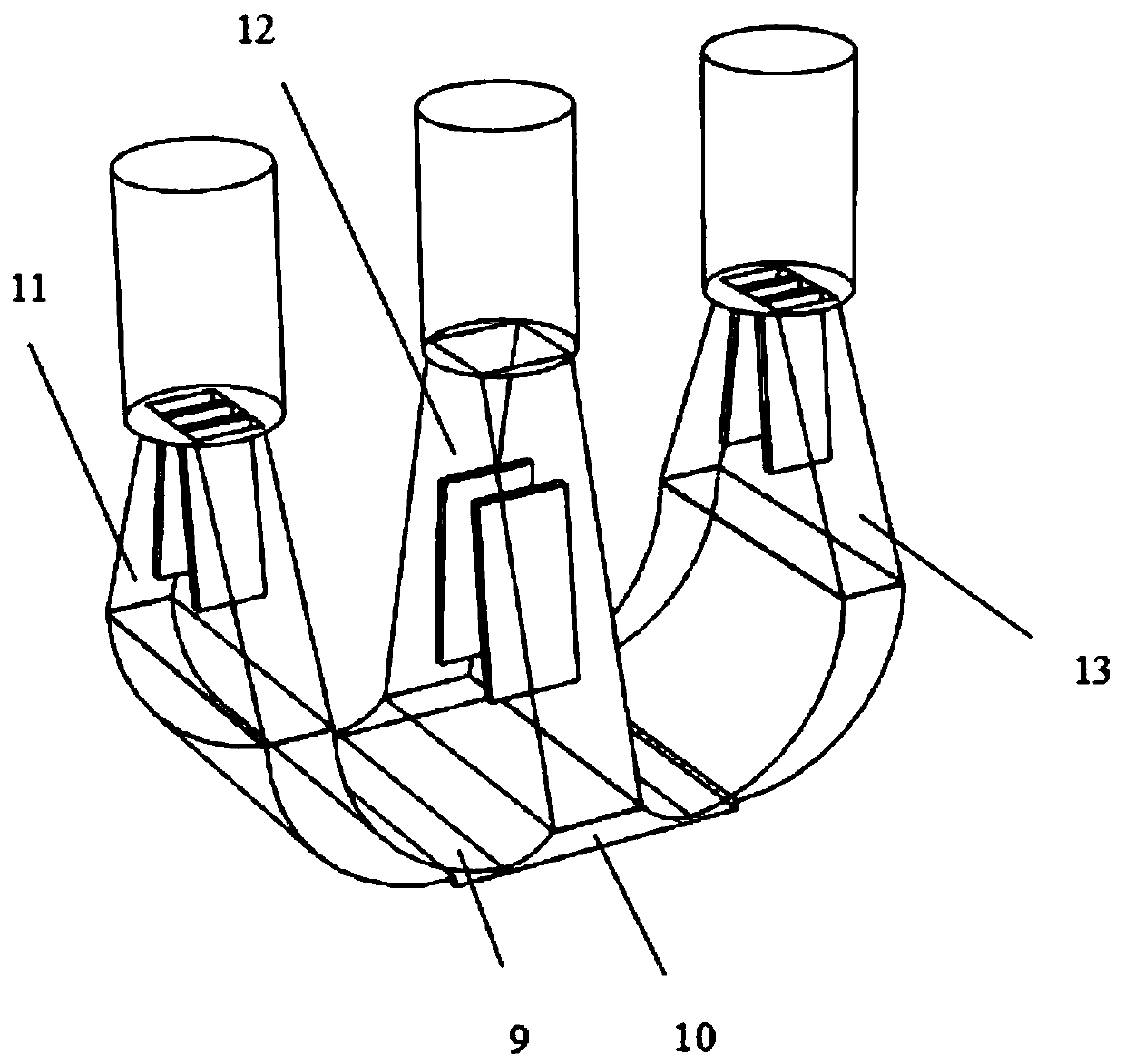
[0039] This embodiment provides a slurry removal assembly 2 for implementing the method of Embodiment 1, including a gas nozzle that can move up and down, and the gas nozzle includes a first positive pressure chamber 11, a negative pressure chamber 12 and a second positive pressure chamber arranged side by side. The bottom of the pressure chamber 13 , the first positive pressure chamber 11 and the bottom of the second positive pressure chamber 13 are respectively provided with a positive pressure slit 9 , and the bottom of the negative pressure chamber 12 is provided with a negative pressure hole 10 . During use, when the slurry removal assembly 2 reaches the top of the preparatory empty foil area 31, the air is blown out from the positive pressure slot 9 to form a positive pressure air outlet knife, and the high-speed air molecules in the positive pressure air outlet air knife impact the coating on the preparatory air foil area. The slurry on the surface of the foil area 31 ma...

Embodiment 3

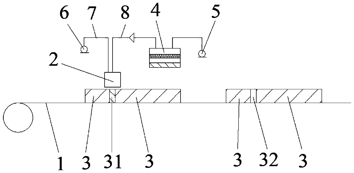
[0042] This embodiment provides a slurry removal system that implements any one of the methods in Embodiment 1, including a slurry collection bucket 4, a vacuum device, and a slurry removal assembly 2. The slurry removal assembly 2 is the slurry described in Embodiment 2. The slurry removal assembly 2, the slurry removal assembly 2 is connected to the slurry collection bucket 4, and the slurry collection bucket 4 is connected to the vacuum device. Wherein, the vacuuming device includes a vacuum pipeline 8 and a vacuum pump 5 connected with the vacuum pipeline 8. When the vacuum pump 5 is turned on, the negative pressure high-speed air will suck the slurry accumulated on the surface of the preparatory empty foil area 31 into the negative pressure cavity 12, and then the vacuum pipeline will 8 enters the slurry collection bucket 4, realizes the separation of gas and slurry in the slurry collection bucket 4, and the slurry accumulated on the surface of the preparatory empty foil a...


PUM


Abstract

The invention belongs to the technical field of lithium ion batteries, and particularly relates to a slurry removing method. The method comprises the steps of 1, arranging a probationary empty foil area on the surface of a current collector, and coating the current collector with slurry to obtain an active substance layer; 2, setting the upper part of the probationary empty foil area as positive pressure so as to enable the slurry on the surface of the probationary empty foil area to be gathered; and 3, setting the upper part of the probationary empty foil area as negative pressure so as to suck the slurry gathered on the surface of the probationary empty foil area to obtain the empty foil area. The method has the advantages of good mass production, no introduction of special consumables,low cost, no damage to the current collector compared with the current mode of scraping part of the active substance layer after drying, and more excellent safety performance of the electrical core.

Description

technical field [0001] The invention belongs to the technical field of lithium-ion batteries, and in particular relates to a slurry removal method and components and systems for realizing the method. Background technique [0002] In recent years, the lithium-ion battery industry has developed rapidly. Lithium-ion batteries have been widely used in all aspects of social life. They have the advantages of high energy density, high voltage, high cycle and high operating temperature. [0003] In order to meet the requirements of fast charging for lithium-ion battery cells, the cell design proposes a battery cell with a center-mounted tab structure. At the manufacturing level, to achieve center-mounted tabs, it is necessary to reserve a welding slot in the middle of the positive and negative electrodes. For the pole piece structure, it is necessary to leave a part of the active material layer coated on the current collector uncoated or remove a part after coating and drying for we...

Claims


Application Information

Patent Timeline
Patent Type & Authority Applications(China)
IPC IPC(8): H01M4/04H01M10/0525H01M10/058
CPCH01M4/04H01M4/0404H01M10/0525H01M10/058Y02E60/10Y02P70/50
Inventor 张文广李国栋纪荣进郑明清陈杰杨山李载波
Owner HUIZHOU LIWINON NEW ENERGY TECH CO LTD
Why Eureka
Try Eureka