Mechanical arm feeding system

A feeding system and manipulator technology, applied in the field of manipulator systems for handling and feeding, can solve the problems of separate collaborative execution, high equipment failure rate, affecting processing rhythm, etc., and achieve the effect of high speed, low investment cost and high production efficiency

Pending Publication Date: 2020-05-01
南京智必达自动化科技有限公司
View PDF0 Cites 4 Cited by
  • Summary
  • Abstract
  • Description
  • Claims
  • Application Information

AI Technical Summary

Problems solved by technology

[0003] However, the actions of the manipulator systems currently on the market are controlled by a separate motor or pneumatic means. Generally, one action is executed after the other action is in place, or the two actions are executed in coordination.
Position control is performed through position sensing switches or other electrical signals. The problem with this solution is that 1. It requires a complex electrical system, which has a high failure rate and complicated maintenance; 2. The equipment is complex and costly, making it difficult to popularize in the market; 3. Due to the need for complex electrical control, its speed is generally not very fast, such as the mainstream 2-axis punch feeding manipulator system in the field market, the general feeding speed is 3-5S, which affects the processing cycle
4. Since the operation synchronization with the processing host is also controlled by electrical signals, if a certain electrical signal fails, such as a sensor switch malfunctioning, it will often lead to equipment damage and serious safety accidents

Method used


Image

  • Mechanical arm feeding system
  • Mechanical arm feeding system
  • Mechanical arm feeding system

Examples


Embodiment Construction

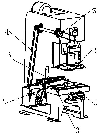
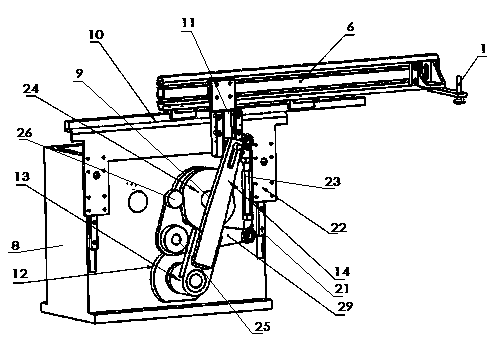
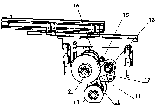
[0030] The figure is an embodiment of the manipulator feeding system of the present invention, including a punching machine, a feeding manipulator 7 arranged on the feeding side of the punching machine, the feeding manipulator is connected to the punch driving device 5 through a chain 4, the feeding manipulator includes a feeding bracket 8, and the feeding manipulator is set The X-axis motion guide rail device on the feeding bracket, the Z-axis motion guide rail device installed on the side of the feeding bracket, the X-axis driving mechanism connected with the X-axis motion guide rail device, and the Z-axis motion guide rail device driving connection The Z-axis drive mechanism, and the main drive shaft 9 that is arranged on the bracket and is connected with the chain through gears and provides the power of the X-axis drive mechanism and the Z-axis drive mechanism; The X-axis guide rail 10 on the top of the bracket is slidably arranged on the X-axis guide rail and the moving me...


PUM


Abstract

The invention discloses a mechanical arm feeding system. The system comprises a punch, and a feeding mechanical arm mounted on the feeding side of the punch, the feeding mechanical arm is in work connection with a punch drive device through a chain, the feeding mechanical arm comprises a feeding support, an X-axis-direction motion guide rail device mounted on the feeding support, a Z-axis-direction motion guide rail device mounted on the side of the feeding support, an X-axis driving mechanism in drive connection with X-axis-direction motion guide rail device, a Z-axis driving mechanism in drive connection with the Z-axis-direction driving mechanism and a main driving shaft mounted on the support, in connection with the chain through a gear and capable of providing power for the X-axis driving mechanism and the Z-axis driving mechanism. The mechanical arm feeding system is high in speed, production efficiency is high, operation is easy and convenient, the equipment structure is simple,investment cost is low, operation is easy, manual operation is not needed, and the mechanical arm can be operated only through operating an equipment main engine.

Description

technical field [0001] The invention relates to a manipulator feeding system, in particular to a manipulator system for handling and feeding. Background technique [0002] With the rise of labor costs, the processing of the workshop is increasingly relying on the manipulator system to replace manual work, especially some simple repetitive or dangerous work, such as forging loading and unloading, stamping loading and unloading, machining loading and unloading, etc. [0003] However, the actions of the manipulator systems currently on the market are all controlled by a separate motor or pneumatic means. Generally, one action is executed after the other action is in place, or the two actions are coordinated separately. Position control is performed through position sensing switches or other electrical signals. The problem with this solution is that 1. It requires a complex electrical system, which has a high failure rate and complicated maintenance; 2. The equipment is complex ...

Claims


Application Information

Patent Timeline
Patent Type & Authority Applications(China)
IPC IPC(8): B21D43/10
CPCB21D43/105
Inventor 戴德纯唐郭
Owner 南京智必达自动化科技有限公司
Why Eureka
Try Eureka