Automatic tray filling device of electronic chip tray filling machine

A technology of electronic chips and loading machines, which is used in conveyors, stacking of objects, and destacking of objects, etc., can solve the problems of difficulty in moving trays, low success rate of unloading trays, and re-opening of reclaiming trays. , to achieve the effect of ensuring one-way passability, preventing movement and improving efficiency

Active Publication Date: 2020-05-01
浙江优众新材料科技有限公司 +2
View PDF9 Cites 2 Cited by
  • Summary
  • Abstract
  • Description
  • Claims
  • Application Information

AI Technical Summary

Problems solved by technology

[0006] The purpose of the present invention is to solve the problems in the existing electronic chip tray loading technology, such as the difficulty in moving the tray, double-folding of the tray, and the low success rate of the tray, to propose a tray that is accurate, efficient in movement, and stackable. The automatic loading device of the electronic chip loading machine with high disk success rate and automatic stacking

Method used


Image

  • Automatic tray filling device of electronic chip tray filling machine
  • Automatic tray filling device of electronic chip tray filling machine
  • Automatic tray filling device of electronic chip tray filling machine

Examples


Embodiment Construction

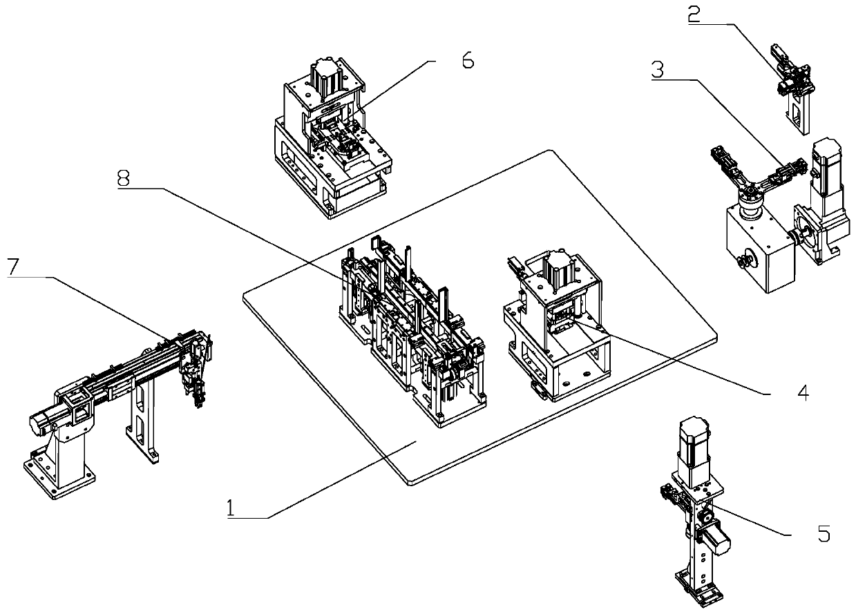
[0028] Such as figure 1As shown, an electronic chip loading machine includes a frame 1 and a distributing device 2 installed on the frame 1, a rotating conveying device 3, a pin pressing device 4, a transition conveying device 5, and a pin cutting device 6 , linear conveying device 7 and loading device 8; rotating conveying device 3 connects material distribution device 2 and pin pressing device 4, and described material distribution device 2 feeding end is provided with chip feeding device; Lead cutting device 6 Set opposite to the pin pressing device 4, the transition transfer device 5 connects the pin pressing device 4 and the pin cutting device 6; the said loading device 8 is arranged on the side of the pin cutting device 6, and transport The device 7 is located above the disk loading device 8 , and the linear conveying device 7 connects the lead cutting device 6 and the disk loading device 8 .

[0029] The distributing device 2 is used to sort out a single electronic chi...


PUM


Abstract

The invention relates to the technical field of electronic chip production. An automatic tray filling device of an electronic chip tray filling machine comprises a base, limiting stand columns, a transmission assembly, a fixture assembly, a tray taking assembly, a tray stacking assembly, a first lock catch assembly and a second lock catch assembly; the base is fixedly arranged on a rack, the limiting stand columns are arranged at the upper end of the base, the base is correspondingly provided with an empty material tray taking station, a tray arranging station and a full stacked material traystation, and the empty material tray taking station and the full stacked material tray station are each correspondingly provided with the four limiting stand columns; the tray taking assembly corresponds to the empty material tray taking station, and the tray stacking assembly corresponds to the full stacked material tray station; the transmission assembly is installed on the base, and the fixtureassembly is installed at the output end of the transmission assembly; and the first lock catch assembly and the second lock catch assembly are installed on the base, the first lock catch assembly corresponds to the empty material tray taking station, and the second lock catch assembly corresponds to the full stacked material tray station. The automatic tray filling device of the electronic chip tray filling machine has the advantages that material tray taking is precise, moving is efficient, the tray stacking success rate is high, and stacking automation is achieved.

Description

technical field [0001] The invention relates to the technical field of electronic chip production, in particular to an automatic disk loading device of an electronic chip disk loading machine. Background technique [0002] After the chip is packaged, it is usually necessary to process the pins, cut off the redundant pins, and finally place the chip in the tray for collection. There are grooves in a rectangular array on the plate. The grooves are used to accommodate chips. When the plate is swung, chips are put into each groove. When each groove on the mold plate is filled with chips, the mold plate Trays are stacked for easy transport of chips to subsequent processing steps. [0003] The State Intellectual Property Office of China has published a patent with a publication number of CN110480702A and a patent name of a production equipment for busbar terminals and a cutting method for busbar terminals, which includes a frame and a shaping device installed on the frame and a c...

Claims


Application Information

Patent Timeline
Patent Type & Authority Applications(China)
IPC IPC(8): B65G47/90B65G47/248B65G59/06B65G57/03B21F11/00
CPCB21F11/00B65G47/248B65G47/904B65G57/03B65G59/061B65G2201/0258
Inventor 王伟波鲁晓沈强益徐建华
Owner 浙江优众新材料科技有限公司
Why Eureka
Try Eureka