Distributed optical fiber sensing device
A technology of distributed optical fiber and sensing device, which is applied in the direction of measuring device, using optical device to transmit sensing components, converting sensor output, etc., can solve the problems of increasing pulse laser, increasing measurement time, sacrificing spatial resolution, etc., and achieve detection Effects of long distance, short measurement time, and cost reduction
- Summary
- Abstract
- Description
- Claims
- Application Information
AI Technical Summary
Problems solved by technology
Method used
Image
Examples
Embodiment 1
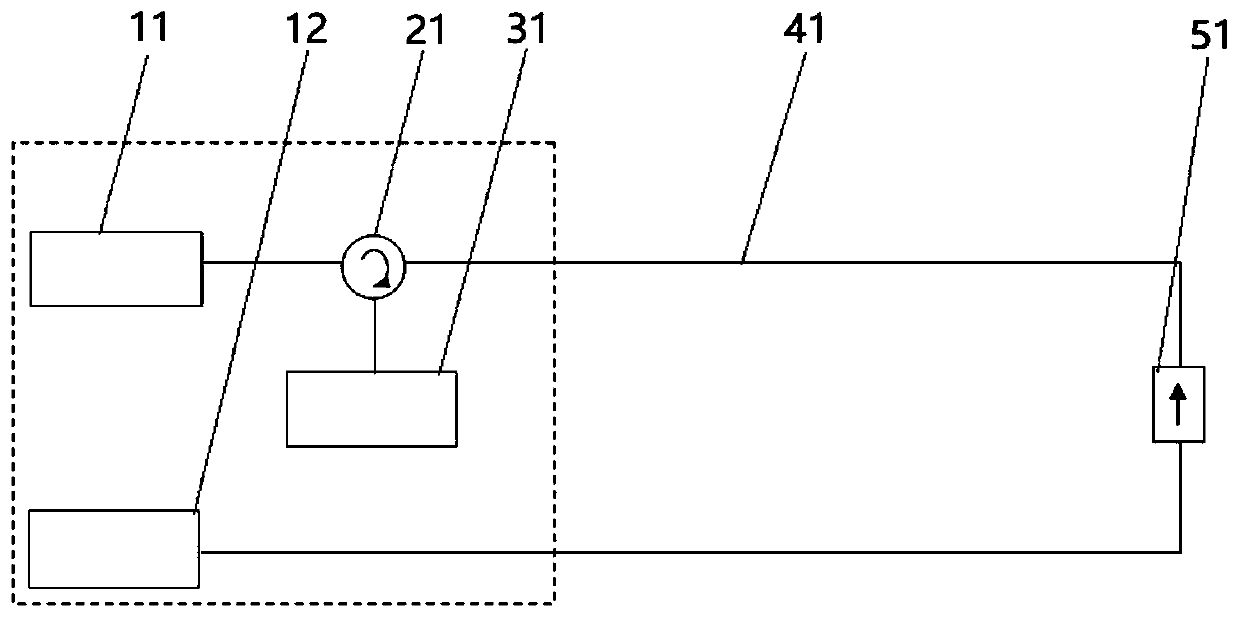
[0040] figure 1 Schematically provides a simplified structural diagram of the distributed optical fiber sensing device of the embodiment of the present invention, such as figure 1 As shown, the distributed optical fiber sensing device includes:
[0041] Loopback optical fiber 41, such as an optical cable not less than a double-core optical fiber, the length of the optical cable is 100 kilometers, and the far end of the optical cable fuses the double-core optical fiber together to form the loopback optical fiber 41. is 200 kilometers;
[0042] Optical fiber circulator 21, such as a three-port optical fiber circulator, the incident laser light enters from the first port and reaches the second port, and the backscattered light enters from the second port and then reaches the third port;
[0043] The detector 31, such as an InGaAs photodetector, is used to detect the backscattered light of the loopback optical fiber 41, and convert the backscattered light into an electrical sign...
Embodiment 2
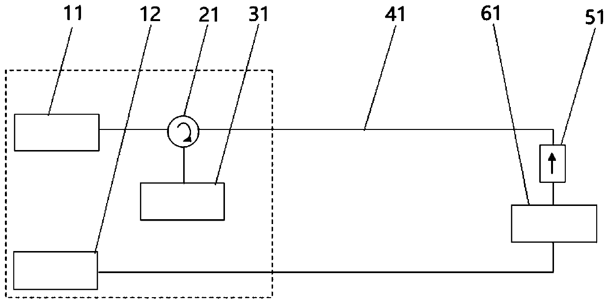
[0053] The distributed optical fiber sensing device according to the embodiment of the present invention is different from Embodiment 1 in that:
[0054] Such as figure 2 As shown, the distributed optical fiber sensing device also includes an optical amplifier 61, and the optical amplifier 61 is located on the upstream or downstream optical path of the blocker 51, and the power of the continuous laser light transmitted backward in the loopback optical fiber 41 is controlled by the optical amplifier 61. Amplifier 61 boosts.
[0055] Since the optical amplifier is located in the middle of the loop-back fiber, and its gain is relatively large, the power of the continuous laser light emitted by the second light source and entering the loop-back fiber can be greatly reduced. When the reverse-transmitted CW laser in the loopback fiber reaches the optical amplifier, the CW laser achieves relay amplification at the optical amplifier, compensating for the transmission loss of the CW ...
Embodiment 3
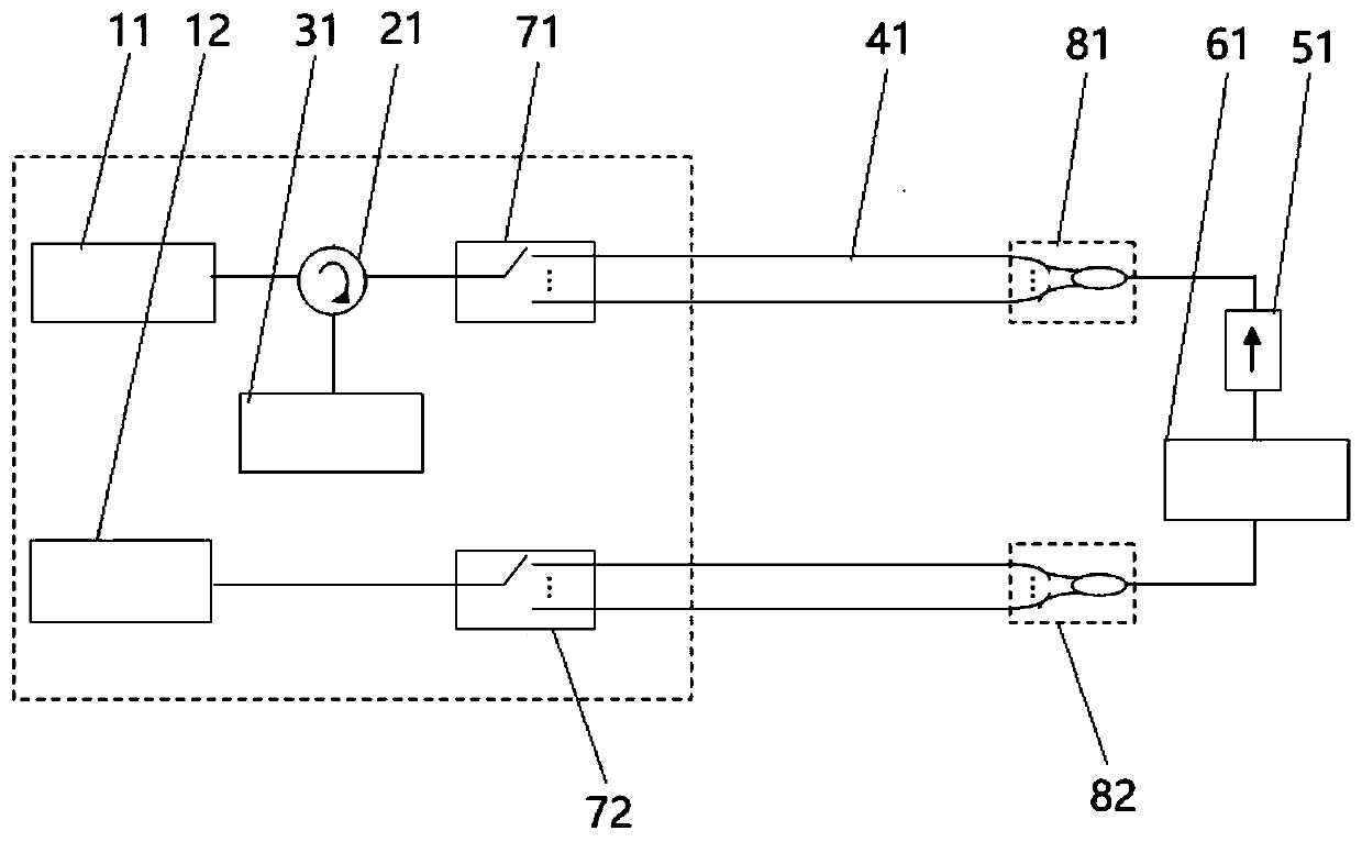
[0059] The distributed optical fiber sensing device according to the embodiment of the present invention is different from Embodiment 2 in that:
[0060] The blocker is built in the optical amplifier, and the blocker is located behind the output end of the optical amplifier, that is, the optical amplifier is a unidirectional optical amplifier, which is convenient for on-site deployment.
[0061] In this embodiment, the optical amplifier is an erbium-doped fiber amplifier EDFA with a working wavelength of 1550±20nm and a gain of 15dB for small signals. The blocker is a one-way two-stage fiber optic isolator with a working wavelength of 1550±20nm, one-way transmission, and an isolation degree greater than 35dB. The unidirectional dual-stage fiber optic isolator is located directly behind the output end of the erbium-doped fiber amplifier EDFA to realize unidirectional small signal amplification. The integrated structure is highly integrated and convenient for on-site deployment....
PUM
| Property | Measurement | Unit |
|---|---|---|
| Center wavelength | aaaaa | aaaaa |
| Isolation | aaaaa | aaaaa |
Abstract
Description
Claims
Application Information
 - R&D
- Intellectual Property
- Life Sciences
- Materials
- Tech Scout
- Unparalleled Data Quality
- Higher Quality Content
- 60% Fewer Hallucinations
Browse by: Latest US Patents, China's latest patents, Technical Efficacy Thesaurus, Application Domain, Technology Topic, Popular Technical Reports.
© 2025 PatSnap. All rights reserved.Legal|Privacy policy|Modern Slavery Act Transparency Statement|Sitemap|About US| Contact US: help@patsnap.com


