MEMS sensor and preparation method thereof

A sensor and device layer technology, which is applied in the field of MEMS sensors and its preparation, can solve the problems of large zero output and achieve the effects of reducing high zero output, improving performance, back-end circuit and processing simplicity

Pending Publication Date: 2020-05-05
AUTOCHIPS WUHAN CO LTD
View PDF7 Cites 2 Cited by
  • Summary
  • Abstract
  • Description
  • Claims
  • Application Information

AI Technical Summary

Problems solved by technology

[0005] The invention provides a MEMS sensor and its preparation method, which mainly solves the technical problem of large zero-point output in the existing technical problems

Method used


Image

  • MEMS sensor and preparation method thereof
  • MEMS sensor and preparation method thereof
  • MEMS sensor and preparation method thereof

Examples


Embodiment Construction

[0029] The following will clearly and completely describe the technical solutions in the embodiments of the present invention with reference to the accompanying drawings in the embodiments of the present invention. Obviously, the described embodiments are only some, not all, embodiments of the present invention. Based on the embodiments of the present invention, all other embodiments obtained by persons of ordinary skill in the art without making creative efforts belong to the protection scope of the present invention.

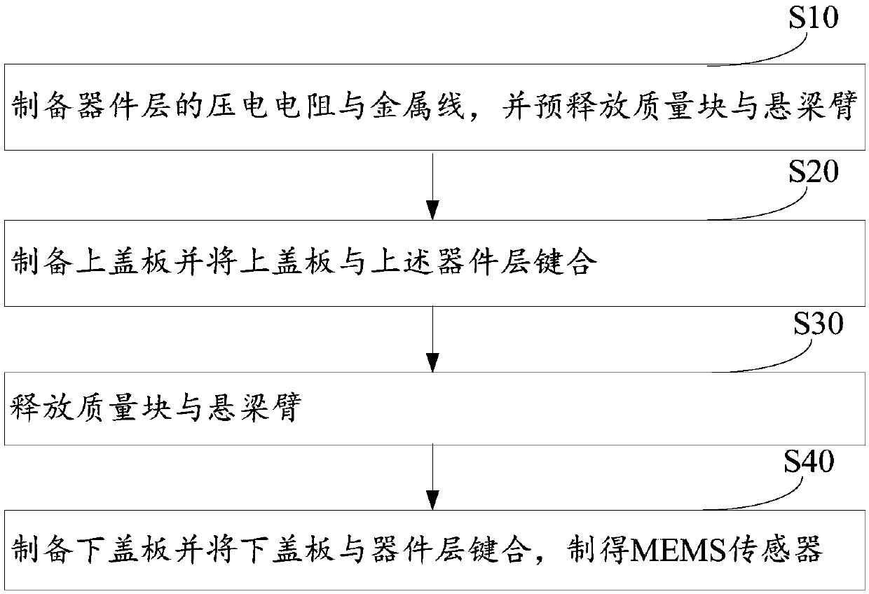
[0030] see figure 2 , the embodiment of the present invention provides a kind of preparation method of MEMS sensor 100, comprises the following steps:

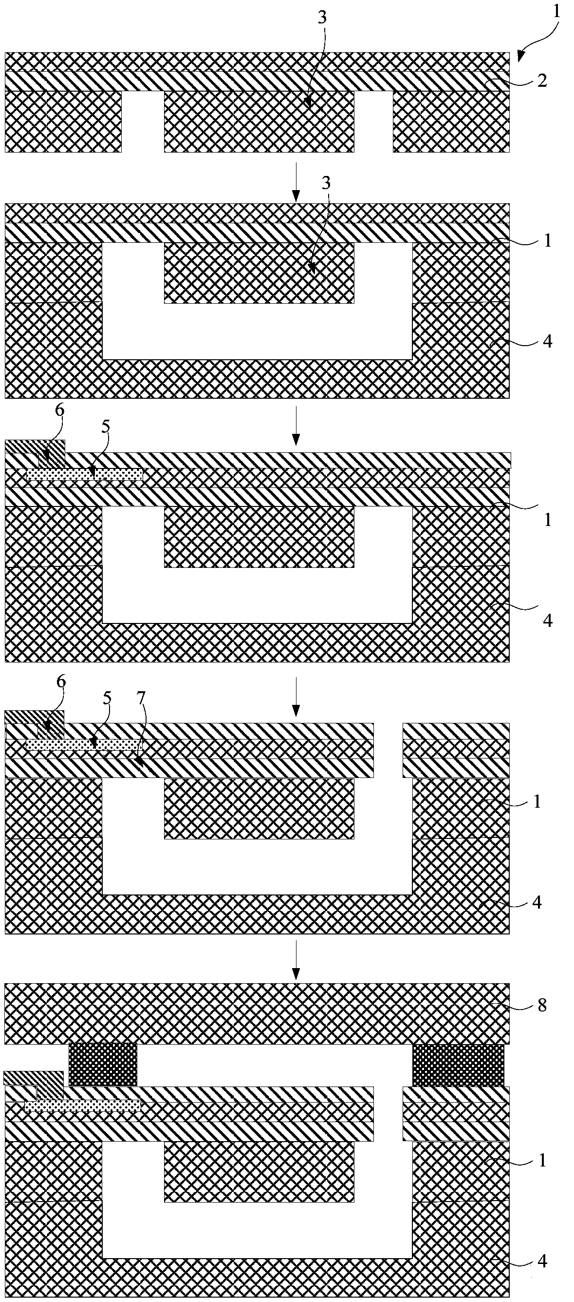
[0031] In step S10 , the piezoelectric resistor 15 and the metal wire 50 of the device layer 10 are prepared, and the proof mass 16 and the cantilever beam 17 are pre-released.

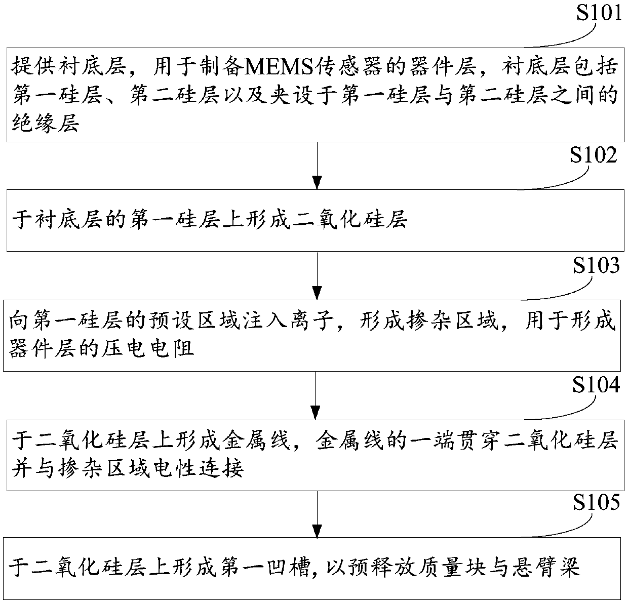
[0032] Specifically, please refer to image 3 , the steps of preparing the piezoelectric resistor 15 and the metal wire 50 of the...


PUM


Abstract

The invention discloses an MEMS sensor and a preparation method thereof, and the preparation method of the MEMS sensor comprises the steps: preparing a piezoelectric resistor and a metal wire of a device layer, and pre-releasing a mass block and a cantilever beam; preparing an upper cover plate and bonding the upper cover plate with the device layer; releasing the mass block and the cantilever beam; and preparing a lower cover plate and bonding the lower cover plate with the device layer to prepare the MEMS sensor. In this way, the MEMS sensor can effectively reduce zero point output.

Description

technical field [0001] The invention relates to the technical field of mechatronics, in particular to a MEMS sensor and a preparation method thereof. Background technique [0002] MEMS sensors, or Microelectro Mechanical Systems (MEMS), is a multidisciplinary cutting-edge research field developed on the basis of microelectronics technology. At present, MEMS sensors are widely used in automobiles, aircraft, aerospace and other fields. [0003] see figure 1 , a method for preparing a MEMS sensor in the prior art, comprising the following steps: step S11, performing a deep silicon etching process on the substrate layer 2 of the device layer 1 to form a mass 3; step S12, performing silicon-silicon bonding treatment , to bond the device layer 1 and the lower cover plate 4; step S13, doping the leads to form the piezoelectric resistor 5 and the metal wire 6; step S14, release the mass 3 and the cantilever beam 7; step S15, the upper The cover plate 8 is bonded to the device laye...

Claims


Application Information

Patent Timeline
Patent Type & Authority Applications(China)
IPC IPC(8): B81C3/00B81C1/00B81B7/02
CPCB81C3/001B81C1/00349B81B7/02
Inventor 阮盛杰
Owner AUTOCHIPS WUHAN CO LTD
Why Eureka
Try Eureka