Carbon dioxide and/or hydrogen sulfide detection system and method and use thereof

A carbon dioxide and detection system technology, applied in climate change adaptation, water testing, measuring devices, etc., can solve problems such as reducing heat

Pending Publication Date: 2020-05-05
BLUE UNIT AS
View PDF8 Cites 2 Cited by
  • Summary
  • Abstract
  • Description
  • Claims
  • Application Information

AI Technical Summary

Problems solved by technology

Third, it is desirable to provide a way to use CO 2 CO detection sensor 2 detection system, the CO 2 The detection sensor reduces the tendency to heat up and cause the problems mentioned above, and the system has the advantages of a centralized measurement system, but without the disadvantages of the prior art
These H 2 S detection has the same disadvantages as discussed above regarding the prior art CO 2 Same drawbacks as described for the detection system

Method used


Image

  • Carbon dioxide and/or hydrogen sulfide detection system and method and use thereof
  • Carbon dioxide and/or hydrogen sulfide detection system and method and use thereof
  • Carbon dioxide and/or hydrogen sulfide detection system and method and use thereof

Examples


Embodiment 1

[0184] Example 1: Regarding CO in Freshwater Samples 2 Gas concentration, comparing two membranes to one membrane.

[0185] The new CO as shown in Figure 1-2 with 2 membranes was first tested 2 Detection system (diagram 1, 2 membranes). Always get 7mg / L free CO 2 gas content. at max CO 2 When the concentration is estimated to be 7mg / L, T 90 (Time to measure 90% of total gas) probably about 4 minutes.

[0186] The new free CO as shown in Figures 1 and 2 with 1 membrane disabled was then tested 2 Detection system (diagram 1, 1 membrane). This setup would correspond to commercially available CO 2 detection system with a single membrane in a membrane block that converts gaseous CO 2 Separation from liquid samples. Obtained free CO 2 The gas content is between 5 and 6mg / L. When the highest CO 2 When the concentration is estimated to be 7mg / L, T 90 Probably about 7 minutes.

[0187] Figure 5a The sample measurement time (in minutes) is shown on the X-axis and the ...

Embodiment 3

[0192] Example 3; Standard diffusion time between measurements

[0193] The new free CO shown in Figure 1-2 with 1 membrane disabled was tested 2 Detection Systems( Figure 5c ), to determine how long it takes for old sample air in the gas circuit to diffuse across the membrane back into the sample water, driven by the gas partial pressure gradient to equilibrium according to Henry's law.

[0194] This test is measuring HCO 3 - Subsequent, where the final concentration in the gas circuit is high.

[0195] This test shows that CO in the air loop 2 It takes about 5-6 minutes for the partial pressure to drop to atmospheric level, or equivalent to 0 mg / l in the sample stream, making it ready for a new measurement.

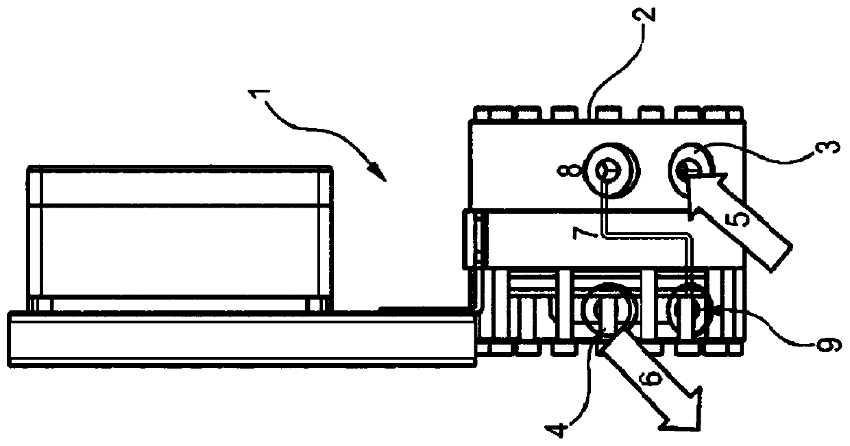
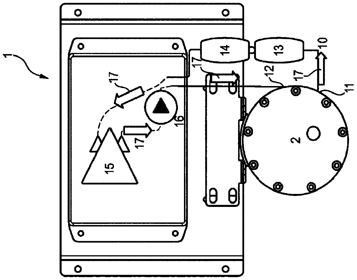
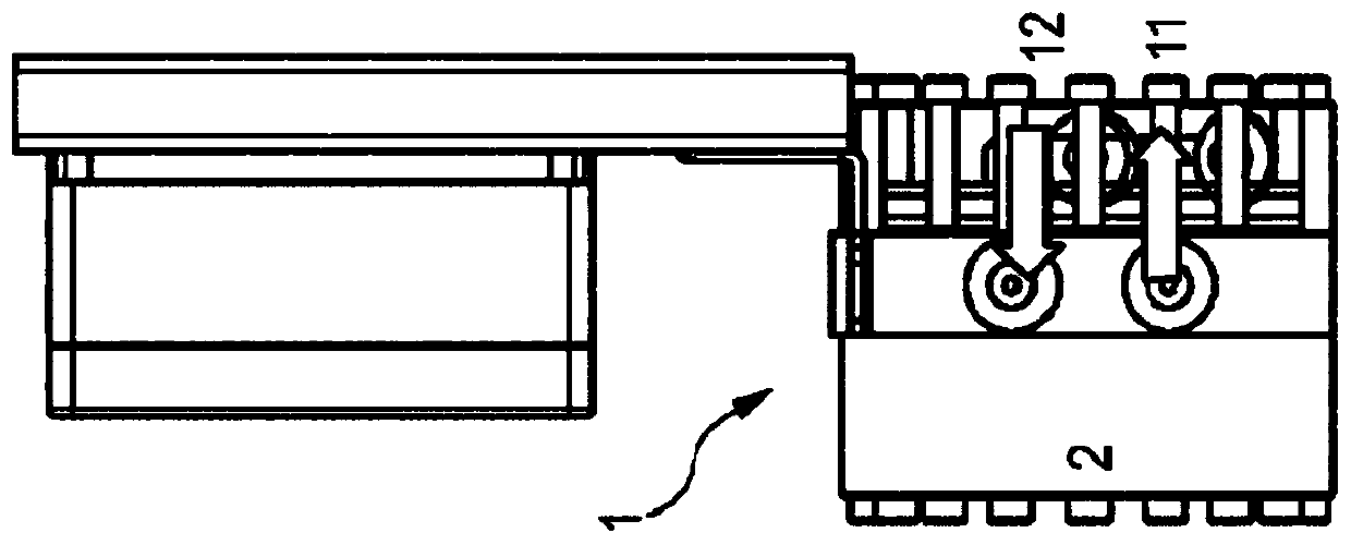
[0196] The detection system shown in Figure 1-2 includes a membrane block, which is combined with a vent valve device to flush out old sample air from the air circuit. The detection system can reach 0 mg / L ( Corresponds to CO in the atmosphere 2 Level).

[01...

Embodiment 4

[0198] Example 4: H 2 S sensor measurements are compared with expected concentrations

[0199] Some tests were performed to evaluate the H as shown in Figure 1-2 2 S detection system, but with H as described above 2 S detection unit 29 instead of CO 2 sensor 15.

[0200] All tests use the same test sample: fresh water, 20°C.

[0201] In all examples, the sequence of operations up to and during the measurement is the same, and as described in Examples 1-3, which concern detection in a device with two membrane units connected in series CO 2 .

[0202] Each test in the examples was repeated with 2 identical test trials. In all tests, the initial removal of free air bubbles was performed using a closed vessel with a space where free air bubbles in the sample stream could be collected and the sample was withdrawn from the bottom of the vessel.

[0203] In all examples, a water sample flow rate of approximately 500 mL / min was used, and in all examples the pressure in the l...


PUM

PropertyMeasurementUnit
pore sizeaaaaaaaaaa
pore sizeaaaaaaaaaa
pore sizeaaaaaaaaaa

Abstract

Carbon dioxide and/or hydrogen sulfide sampling and detection system and method for determination of the content of gaseous CO2 and/or H2S in aqueous liquids, and/or for the fast and reliable detection of the free CO2 gas, HCO3- and/or total carbonate and/or H2S content in aqueous liquids. Said detection system comprises a membrane block having a liquid sample inlet port and a sample outlet port between which a sample flow path extends. Said membrane block comprises a first membrane unit having a sample flow on the first side of a first permeable membrane element and a carrier gas flow on thesecond side of the first permeable membrane element. Said membrane block further comprises a second membrane unit having a sample flow on the first side of a second permeable membrane element and a carrier gas flow on the second side of the second permeable membrane element. Said first and second membrane units are arranged in series in the liquid sample flow path. The gas flow path is a closed loop that includes gas circulation means, the second gas containing side of the first and second membrane units. The system further comprises a carbon dioxide gas sensor and/or a hydrogen sulfide detection unit, which are arranged in the closed gas circulation loop.

Description

technical field [0001] The invention relates to a sampling and detection system for carbon dioxide and / or hydrogen sulfide, which is used to determine the gaseous CO in liquids, especially aqueous liquids 2 and / or H 2 S content, and / or for detecting the total carbonate content in the aqueous liquid, wherein the CO 2 and / or H 2 The S sampling and detection system includes a membrane block having a liquid sample inlet and a liquid sample outlet with a sample flow path extending between the liquid sample inlet and the liquid sample outlet. [0002] The invention also relates to a carbon dioxide and / or hydrogen sulfide sampling and detection method. Background technique [0003] Today, fish are increasingly being farmed in land-based recirculating aquaculture systems (RAS). Ensuring consistent water quality is critical to ensure optimal fish performance in terms of growth rate, feed conversion and fish welfare. Central to the stabilization of fish pond water quality is an u...

Claims


Application Information

Patent Timeline
Patent Type & Authority Applications(China)
IPC IPC(8): G01N33/18
CPCG01N21/3504G01N21/3577G01N33/18G01N33/182G01N33/1893G01N21/85G01N27/27G01N27/40G01N27/413G01N33/004G01N33/0044
Inventor 大卫·亚历山大·欧文
Owner BLUE UNIT AS
Why Eureka
Try Eureka