Claw type ultrasonic transducer

An ultrasonic transducer and transducer technology, applied in the direction of fluid using vibration, etc., can solve the problems of power limitation, low uniformity of radiation sound field, and uniformity of sound field in a single sound radiation direction, so as to improve uniformity and improve The effect of sound radiation efficiency and sound field range

Pending Publication Date: 2020-05-08
ZHEJIANG NORMAL UNIVERSITY
View PDF3 Cites 1 Cited by
  • Summary
  • Abstract
  • Description
  • Claims
  • Application Information

AI Technical Summary

Problems solved by technology

[0003] The traditional multi-frequency drive longitudinal-bend composite mode ultrasonic transducer mainly has the following problems: 1. The electromechanical parameters at the common frequency of multiple vibration modes are different, which leads to difficulties in power supply matching; 2. The distribution of stress and vibration velocity under multiple vibration modes is different , the position of the displacement node is different, and the mechanical fixation is difficult; 3. There is mutual coupling between multiple vibration modes
The existing rod-shaped and tube-shaped liquid-handling ultrasonic transducers are widely used through the mode conversion between longitudinal vibration or longitudinal-radial vibration, which can achieve strong radiated sound power. The working principle of the type transducer is to longitudinally excite the rod or tube to generate radial acoustic radiation. Since the longitudinal wave velocity in the rod or tube is relatively large, the longitudinal wave wavelength is relatively long, and the radiated sound field has a large along the length of the rod or tube. Inhomogeneity, there is a large standing wave characteristic
[0004] The patent with the application number CN200520075667.4 titled "High-Power Ultrasonic Transducer" discloses a high-power transducer capable of generating radial vibration in the circumferential direc

Method used


Image

  • Claw type ultrasonic transducer
  • Claw type ultrasonic transducer
  • Claw type ultrasonic transducer

Examples


Embodiment Construction

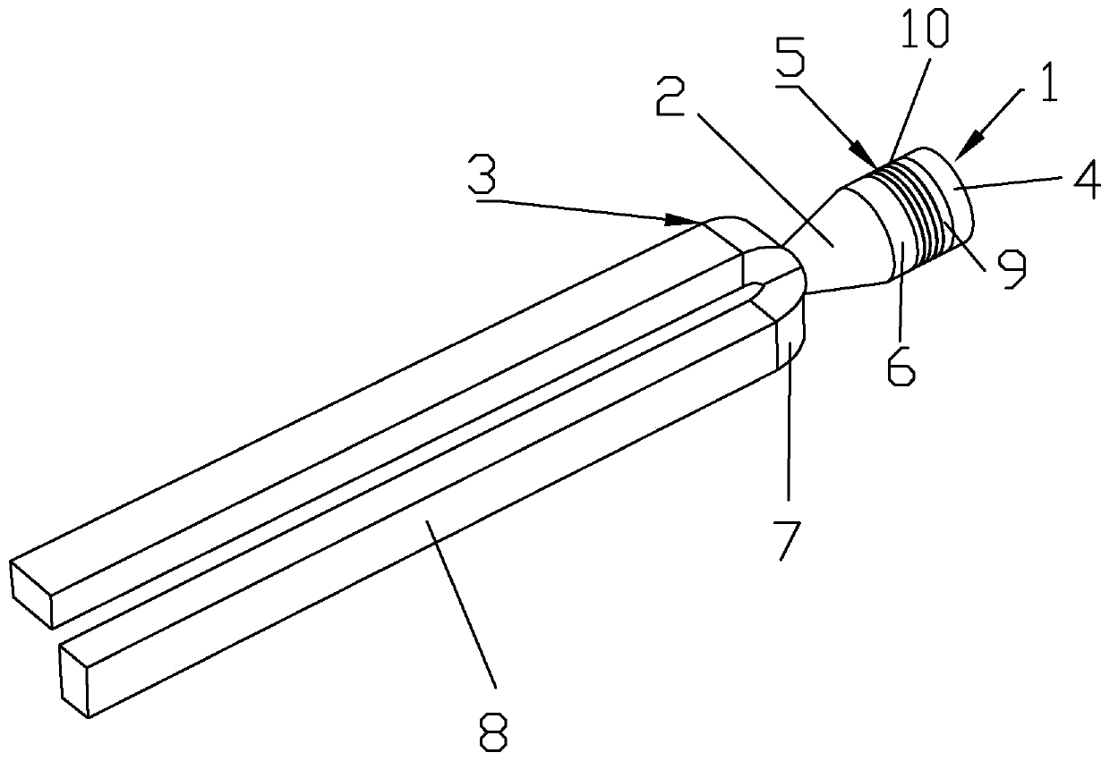
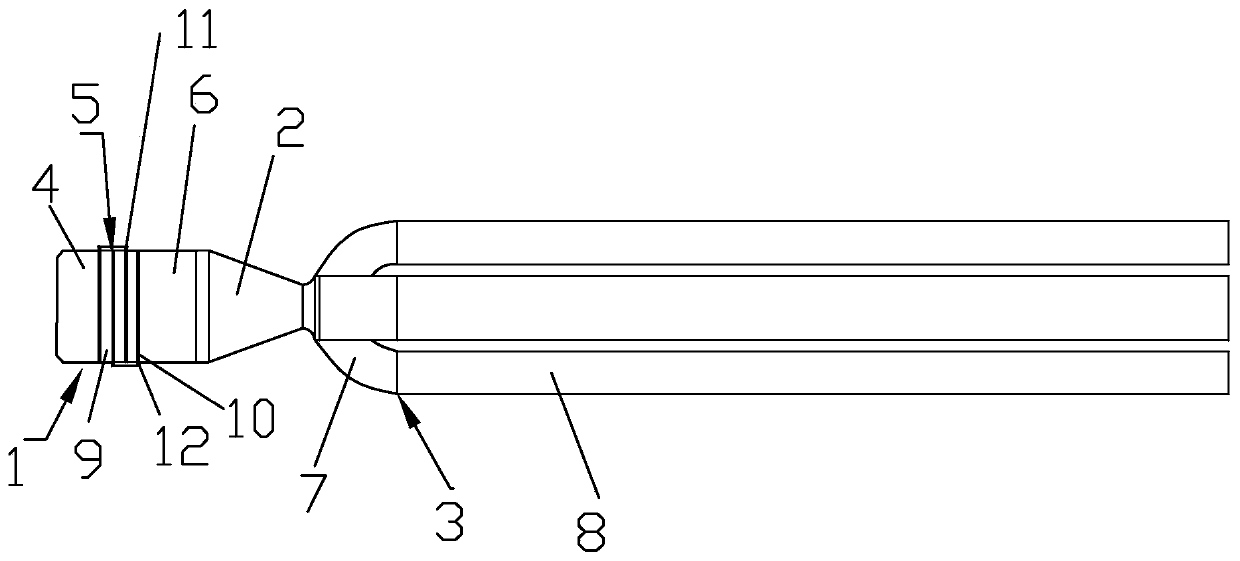
[0030] like Figure 1 to Figure 4Shown is a claw-type ultrasonic transducer of the present invention, including a sandwich-type piezoelectric ultrasonic transducer 1, a horn 2 and a claw-type omnidirectional radiator 3, and one end of the horn 2 is connected to a sandwich-type piezoelectric transducer. The ultrasonic transducer 1 is fixedly connected, and the other end of the horn 2 is fixedly connected with the claw-type omnidirectional radiator 3. The sandwich-type piezoelectric ultrasonic transducer 1 includes a rear cover 4, a piezoelectric ceramic crystal stack 5 and a front cover Plate 6, rear cover plate 4, piezoelectric ceramic crystal pile 5 and front cover plate 6 are fixed together by stress bolts, claw type omnidirectional radiator 3 includes claw bottom 7 and claw finger 8, one end of claw bottom 7 is connected to the amplitude The rod 2 is fixedly connected, and the claw finger 8 is fixedly connected to the other end of the claw bottom 7. The claw bottom 7 is an ...


PUM


Abstract

The invention discloses a claw type ultrasonic transducer. The claw type ultrasonic transducer comprises a sandwich type piezoelectric ultrasonic transducer, a amplitude-changing pole and a claw typeomnidirectional radiator, wherein one end of the amplitude-changing pole is fixedly connected with the sandwich type piezoelectric ultrasonic transducer, and the other end of the amplitude-changing pole is fixedly connected with the claw type omnidirectional radiator; the sandwich type piezoelectric ultrasonic transducer comprises a rear cover plate, a piezoelectric ceramic crystal heap, and a front cover plate, and the rear cover plate, the piezoelectric ceramic crystal heap and the front cover plate are fixed together through stress bolts; and the claw type omnidirectional radiator comprisesa claw bottom and clamp fingers, one end of the claw bottom is fixedly connected with the amplitude-changing pole, the claw fingers are fixedly connected to the other end of the claw bottom, the clawbottom is of an open type structure, the plurality of claw fingers are arranged, and the claw fingers are uniformly distributed in the circumferential direction of the claw bottom. 360-degree omnidirectional acoustic radiation is achieved through the high-order bending vibration mode while high frequency and high power are achieved so that the acoustic radiation efficiency and the sound field action range can be improved, and the uniformity of a radiation sound field can be improved.

Description

technical field [0001] The invention belongs to the technical field of ultrasonic transducers, in particular to a claw-type ultrasonic transducer. Background technique [0002] The function of the ultrasonic transducer is to convert the input electrical power into mechanical power (that is, ultrasonic waves) and then transmit it out, while consuming a small part of the power itself. In high-power ultrasonic application technology fields such as high efficiency, energy saving, and environmental protection, such as ultrasonic cleaning, ultrasonic drug extraction, ultrasonic biofuel equipment, crude oil viscosity reduction, ultrasonic sewage treatment, and sonochemical reactions, the uniformity of the ultrasonic radiation sound field has always been attention of the industry. Especially for liquid medium ultrasonic treatment transducers, in addition to large acoustic power, it is also necessary to have a very large volume deformation to improve the efficiency of ultrasonic ene...

Claims


Application Information

Patent Timeline
IPC IPC(8): B06B1/06B06B3/02
CPCB06B1/0651B06B3/02
Inventor 刘世清麻磊磊周光平
Owner ZHEJIANG NORMAL UNIVERSITY
Why Eureka
Try Eureka