Modified wave cam and design method thereof, wave generator and harmonic reducer

A design method and wave generator technology, applied in the direction of cam, mechanical equipment, gear transmission, etc., can solve the problem that the life of the harmonic reducer, the bearing capacity and the transmission accuracy cannot reach the reducer, the cam curve expression is not detailed enough, Harmonic reducers are not precise enough to achieve the effect of fast calculation speed, accurate design and improved accuracy

Active Publication Date: 2020-05-08
HUBEI KEFENG TRANSMISSION EQUIP CO LTD
View PDF9 Cites 3 Cited by
  • Summary
  • Abstract
  • Description
  • Claims
  • Application Information

AI Technical Summary

Problems solved by technology

For example, the most commonly used elliptical cam wave generator at present, the elliptical cam is more convenient for the deformation control of the wave generator cam, and the design of the outer curve is relatively simple, but the stress on the flexwheel on the long axis of the cam is relatively large, and at the same time The number of tooth pairs is small, which causes the life, load capacity and transmission accuracy of the harmonic reducer to fail to meet the requirements of industrial development for the reducer
[0005] At present, there have been some research results on the design of the outer peripheral curve of the wave generator cam, but there are still the following problems: the long axis part of the commonly used standard elliptical wave generator cam has a small meshing tooth area, and the stress on the flexspline at this position is too large , will accelerate the destruction of the harmonic reducer
The cam curve expression of the improved non-standard elliptical wave generator is not detailed enough, the value allocation method is not perfect enough, there are interference, interference and stress concentration problems, resulting in the harmonic reducer is not precise enough

Method used


Image

  • Modified wave cam and design method thereof, wave generator and harmonic reducer
  • Modified wave cam and design method thereof, wave generator and harmonic reducer
  • Modified wave cam and design method thereof, wave generator and harmonic reducer

Examples


Embodiment Construction

[0033] The present invention will be further described below in conjunction with drawings and embodiments.

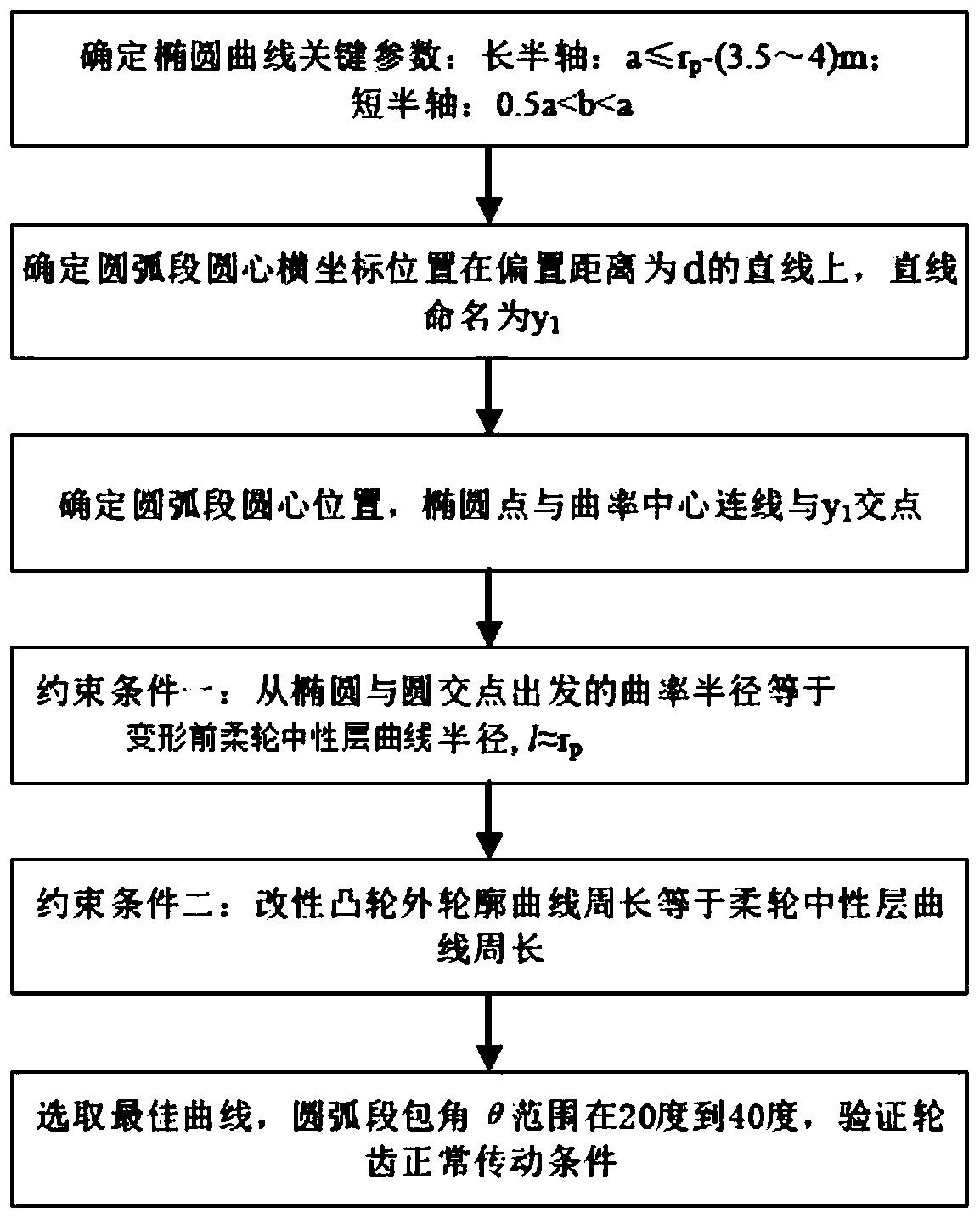
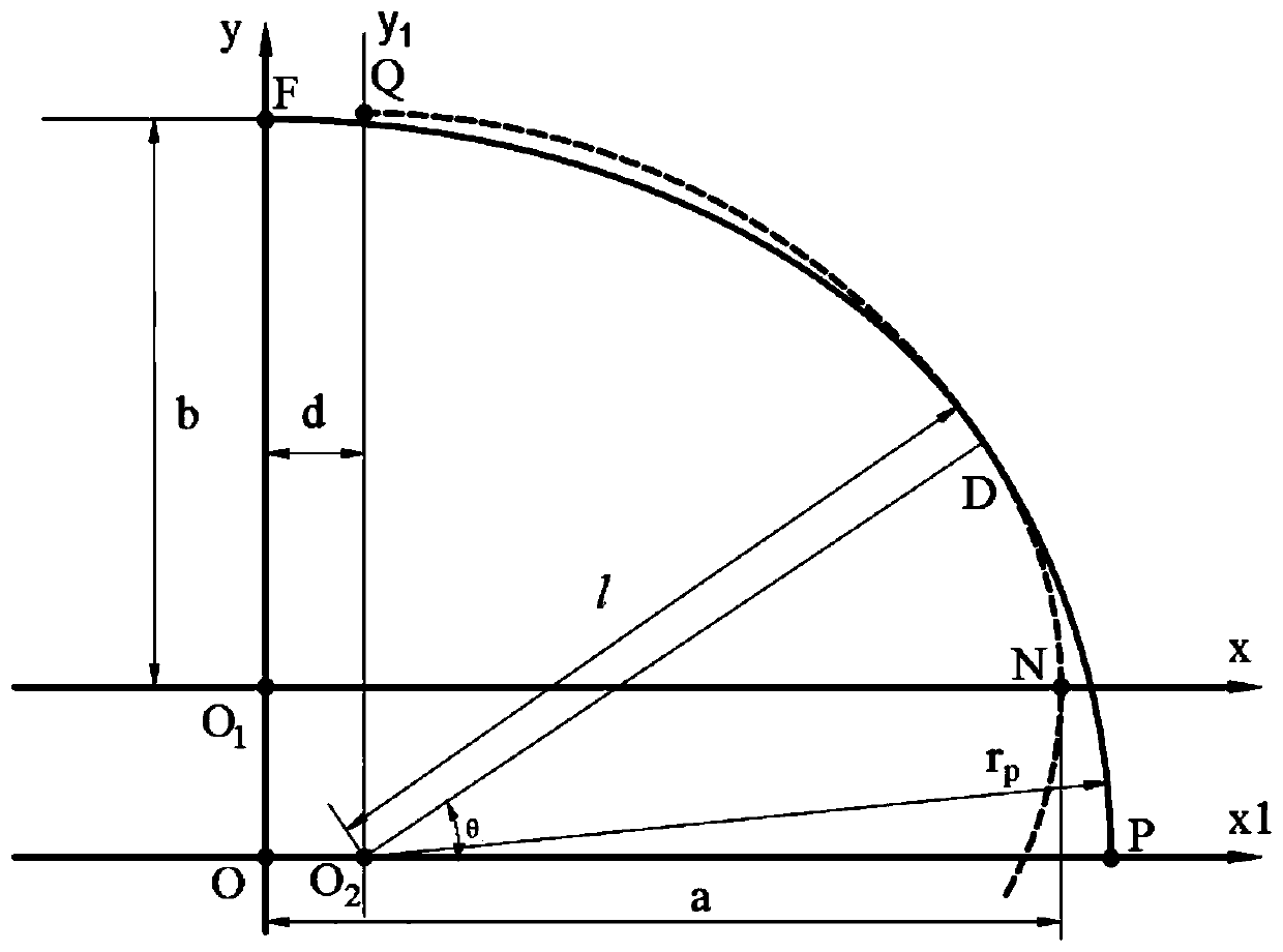
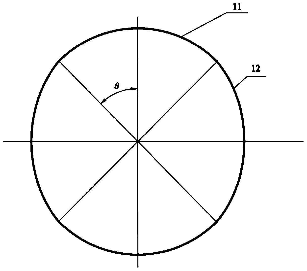
[0034] The outer peripheral curve of the modified wave cam in the embodiment of the present invention is a combination of two circular and two elliptical curves. The circular arcs are at 180° opposite positions. The curve and the arc curve are smoothly connected at the junction, which requires the slope of the two to be the same at the transition point.

[0035] Furthermore, there are two constraints in the design of the curve. In order to ensure good meshing between the deformed flexspline and the rigid spline, the peripheral curve of the modified wave cam needs to expand the flexspline to the meshing position of the rigid spline during the rotation process. It is required that the diameter of the arc after a certain offset is the same as the diameter of the flexspline before deformation. Based on the assumption that the neutral layer curve of the flexspline is not elo...


PUM


Abstract

The invention provides a design method of a modified wave cam. The design method comprises the following steps that a quarter elliptic curve is initially confirmed; the position of the horizontal coordinate of the circle center of a quarter arc is confirmed; the position of the vertical coordinate of the circle center of the quarter arc is confirmed; a quarter curve of the outline of the modifiedwave cam is initially confirmed; the quarter curve of the outline of the modified wave cam is confirmed; the curve is offset inwards; and the complete outline curve of the modified wave cam is confirmed. The modified wave cam is designed out according to the above design method. A wave generator comprises the above modified wave cam and a flexible bearing arranged on the outer edge of the modifiedwave cam. A harmonic reducer at least comprises the above wave generator, a flexible wheel, a rigid wheel and a modified wave cam. According to the modified wave cam designed through the design method and the harmonic reducer, gear tooth interference is avoided, the maximum stress and stress concentration of the flexible wheel in alternating stress changes are reduced, the tooth engagement area between the flexible wheel and the rigid wheel is added, the bearing capacity and precision of the harmonic reducer are improved, and the service life of the harmonic reducer is prolonged.

Description

technical field [0001] The invention relates to a modified wave cam and a design method thereof, a wave generator and a harmonic reducer, and belongs to the technical fields of mechanical processing and harmonic reducer. Background technique [0002] The harmonic reducer was born in the 1950s and is considered a major breakthrough in the field of mechanical transmission. It is widely used in aerospace, robotics, radar, precision machine tools, instrumentation and other fields. The harmonic reducer is mainly composed of three major components, the flexible spline, the rigid spline, and the wave generator. It is a transmission method that relies on the elastic deformation of the flexible gear to transmit force and motion. It is popular because of its simple structure, large transmission ratio, high transmission precision and high transmission efficiency. [0003] The wave generator is a component that deforms the flexspline to generate deformation waves. It is one of the impo...

Claims


Application Information

Patent Timeline
Patent Type & Authority Applications(China)
IPC IPC(8): F16H53/02F16H49/00F16H55/08F16H1/32
CPCF16H53/025F16H49/001F16H55/0826F16H55/0833F16H1/32
Inventor 吴俊峰
Owner HUBEI KEFENG TRANSMISSION EQUIP CO LTD
Why Eureka
Try Eureka