A Helical Resonator for Generating Localized Orbital Angular Momentum
An orbital angular momentum and helix technology, applied in resonators, waveguide devices, circuits, etc., can solve the problem of not guaranteeing the angular momentum of electromagnetic waves, and achieve the effect of enhancing chiral asymmetry and reducing radiation loss.
- Summary
- Abstract
- Description
- Claims
- Application Information
AI Technical Summary
Problems solved by technology
Method used
Image
Examples
Embodiment 1
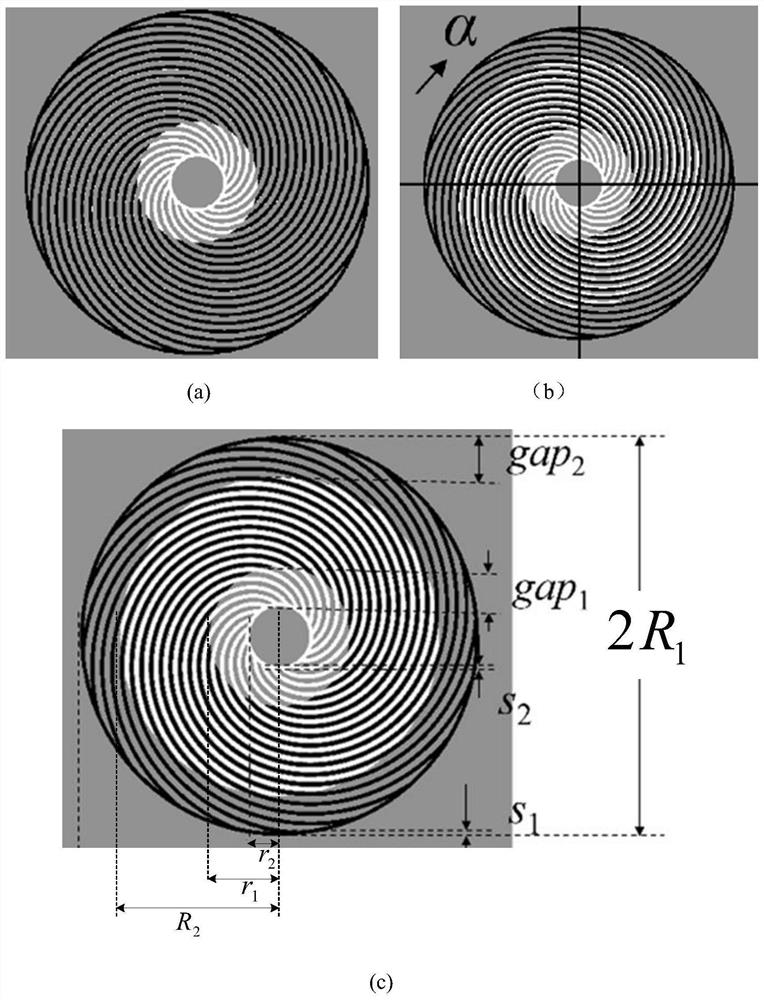
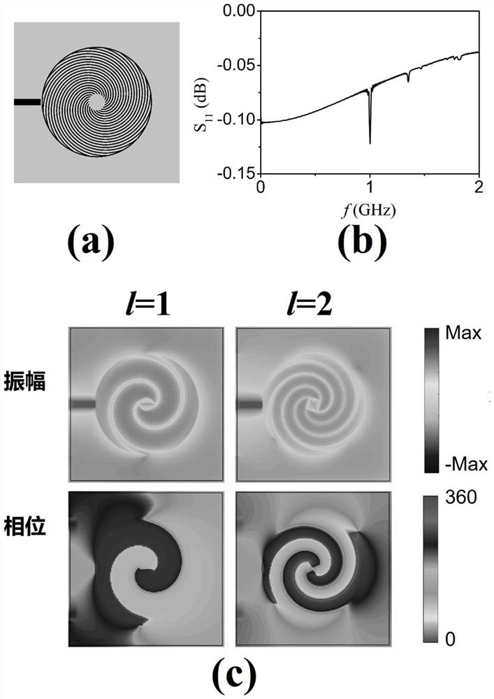
[0037] The gap in the helical resonator of this embodiment 1 =gap 2 =0, namely the first metal helical wire structure and the second complementary helical wire structure have the same large circle radius and small circle radius, R 1 =R 2 = 10mm, r 1 = r 2 = 1.5mm, the width s of the inner and outer circles 1 =s 2 =0.2mm, the width of the metal helix and the width of the complementary helix are both 0.2mm, and its structure is as follows image 3 - Shown in (a). In this embodiment, the resonator adopts a symmetrical microstrip slot coupling excitation mode, and the gap between the end face of the microstrip line and the resonator is 0.2 mm. S in this case 11 spectral lines such as image 3 -shown in (b). Because the coupling efficiency of this excitation method is low, and it is symmetrical excitation. Depend on image 3 -The amplitude and phase of the z component of the electric field in (c) (the z direction is the direction perpendicular to the paper surface), the...
Embodiment 2
[0041] The coupling efficiency in the first embodiment is low, and the excitation structure is a symmetrical structure, and the helical phase plane of the orbital angular momentum is not uniform. In order to improve the uniformity of the helical phase plane, it is necessary to further increase the chiral asymmetry of the resonator, or use an asymmetric excitation method. This embodiment adopts an asymmetric excitation method to further enhance the chiral asymmetry of the entire structure, improve excitation efficiency, and realize a uniform spiral phase plane and high-order orbital angular momentum.
[0042] The structure of the resonator used in this embodiment is the same as that of Embodiment 1, and the excitation structure is as follows Figure 4 As shown in -(a), a 120° microstrip arc is used for excitation. The microstrip arc excitation includes a straight line part and an arc line part; the end of the straight line part is connected to the arc line part. In order to ens...
Embodiment 3
[0044] The difference between this embodiment and Embodiment 2 is that in this embodiment, a 180° microstrip arc is used for excitation. In the microstrip arc excitation, the connection point between the end of the straight line and the arc part divides the arc into two parts of 120° and 60°. The structure is as follows Figure 5 - Shown in (a). S 11 spectral lines such as Figure 5 - As shown in (b), the amplitude and phase of the z component of the electric field are as Figure 5 -(c) (z is the direction perpendicular to the paper surface), electric dipoles, electric quadrupoles, and electric hexapoles correspond to orbital angular momentums of l=1, 2, and 3, respectively. The modes and field constraints of its electric dipole (l=1), electric quadrupole (l=2), electric hexapole (l=3) are all basically the same as embodiment two, but the excitation efficiency of l=1 The increase is 80%, and the excitation efficiency of l=2 and l=3 is almost unchanged.
PUM
 Abstract
Description
Claims
Application Information
 - R&D
- Intellectual Property
- Life Sciences
- Materials
- Tech Scout
- Unparalleled Data Quality
- Higher Quality Content
- 60% Fewer Hallucinations
Browse by: Latest US Patents, China's latest patents, Technical Efficacy Thesaurus, Application Domain, Technology Topic, Popular Technical Reports.
© 2025 PatSnap. All rights reserved.Legal|Privacy policy|Modern Slavery Act Transparency Statement|Sitemap|About US| Contact US: help@patsnap.com


