A kind of steel structure automatic welding production method

A technology of automatic welding and production methods, applied in the direction of welding equipment, welding equipment, auxiliary welding equipment, etc., can solve the problems of long construction period and low efficiency, and achieve the effect of good welding quality, simple process and improved efficiency

Active Publication Date: 2022-01-18
哈工大机器人南昌智能制造研究院
View PDF4 Cites 0 Cited by
  • Summary
  • Abstract
  • Description
  • Claims
  • Application Information

AI Technical Summary

Problems solved by technology

The steel structure of the existing three-dimensional garage is mostly produced by manual welding and installation, which has a long construction period and low efficiency

Method used


Image

  • A kind of steel structure automatic welding production method
  • A kind of steel structure automatic welding production method
  • A kind of steel structure automatic welding production method

Examples


Embodiment 1

[0050] This embodiment discloses a steel structure automatic welding production method, the method includes the following steps:

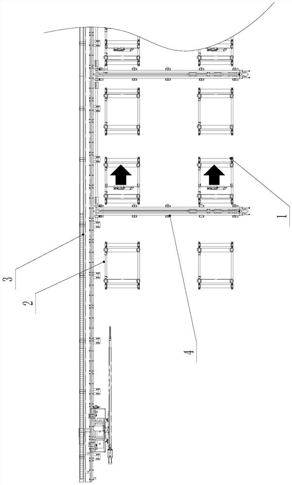
[0051] S1. Place the profiled steel on the buffer lifting conveying roller line 1 at the highest position;

[0052] S2. The buffer lifting conveying roller line 1 descends to drop the profiled steel onto the first transverse conveyor 4, and the first transverse conveyor 4 laterally sends the profiled steel to the top of the first lifting conveying roller line 22 at the lowest position;

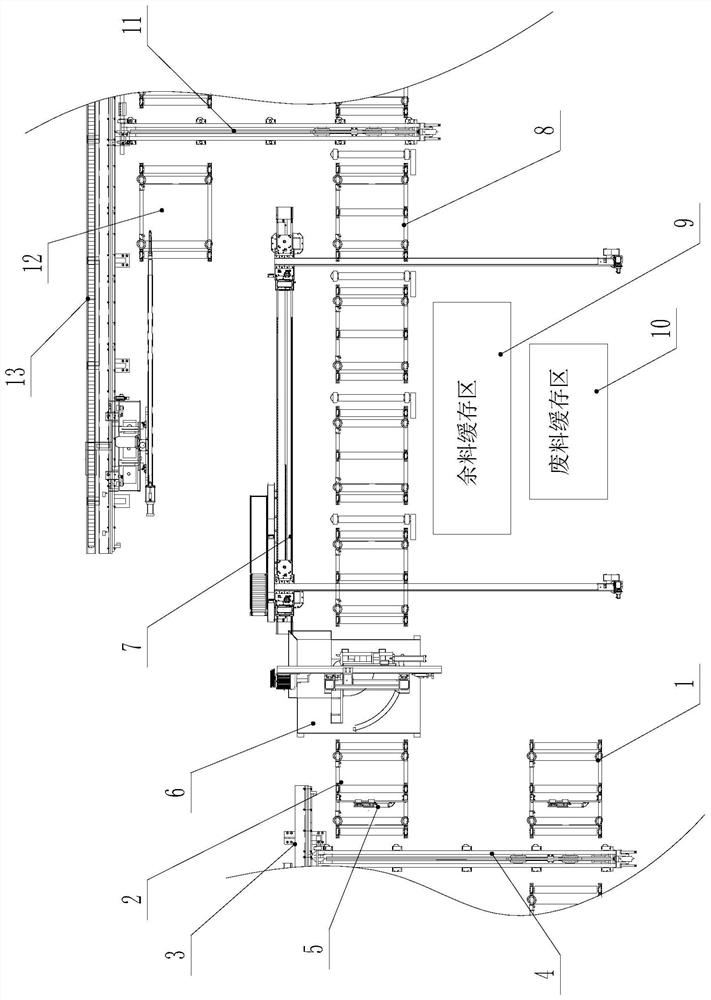
[0053] S3, the first lifting conveying roller line 2 rises to support the section steel, and the section steel is sent to the automatic cutting machine 6 for fixed-length cutting by the fixed-length cutting feeding mechanism;

[0054] S4. The section steel cut to length is conveyed by the second lifting conveying roller line 8; and the remaining material and waste are sent to the remaining material buffer area 9 and the waste material buffer area 10 respectively by...

Embodiment 2

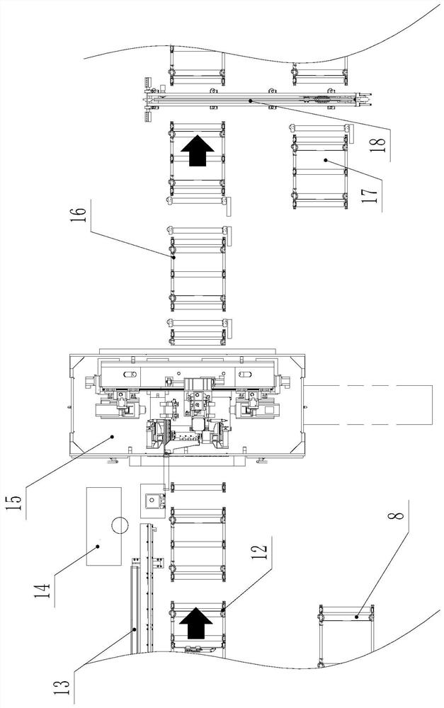
[0079] This embodiment discloses the automatic welding production line that realizes above-mentioned automatic welding production method, as Figure 1 to Figure 5 As shown, an automatic welding production line for steel structures includes a buffer lifting conveyor line 1 and a first lifting conveyor roller line 2 parallel to each other, and a first Horizontal conveyor 4; the downstream of the first lifting conveying roller line 2 is provided with an automatic cutting machine 6, and the side of the first lifting conveying roller line 2 is provided with a fixed-length cutting feeding mechanism 3;

[0080] Among them, the specific structures of the lifting and conveying roller lines mentioned in the embodiment of the present invention (the cache lifting and conveying roller line 1, the first to the seventh lifting and conveying roller lines 25) are all the same, and they all include several lifting and conveying roller group units , each elevating conveying roller group unit is ...


PUM


Abstract

The invention discloses a production method for automatic welding of steel structures. In the method, profiles are transported to an automatic cutting machine for fixed-length cutting, and the cut and waste materials are respectively sent to a surplus material buffer area and a waste material buffer area; the profile steel is sent to The holes are drilled in the automatic drilling device, and then sent to the positioner for automatic welding. During the welding process, the angle of the profile steel is changed according to the welding needs, and the automatic loading of the plate parts is realized by the feeding robot, and the final welding The completed steel structure is sent out. The steel structure automatic welding production method can realize the automatic welding of the steel structure, thereby improving the welding efficiency and the stability of the welding quality.

Description

technical field [0001] The invention relates to an automatic welding production method for a steel structure. The automatic welding production method can automatically weld section steel and plate parts, and belongs to the field of automatic welding. Background technique [0002] Steel structure is a commonly used supporting component, used in various machinery industries, and three-dimensional garage, as one of the typical representatives of prefabricated steel structure buildings, is also called mechanical parking equipment and mechanical three-dimensional parking garage. A general term for parking facilities. Specifically, it is the machinery or mechanical equipment system used to store and store vehicles in the largest number. The mechanical three-dimensional parking garage is a parking equipment assembled by using the steel structure as the main frame, cooperating with the lifting and traversing devices, and the control system. It is an effective way to solve the actua...

Claims


Application Information

Patent Timeline
Patent Type & Authority Patents(China)
IPC IPC(8): B23P23/06B23K37/04B23K37/02B23K10/00
CPCB23K37/0443B23K37/0252B23K10/00
Inventor 丰俊奇赵亮
Owner 哈工大机器人南昌智能制造研究院
Why Eureka
Try Eureka