Combined electron beam additive manufacturing device and process

A technology of additive manufacturing and electron beam, which is applied in the field of electron beam additive printing equipment, can solve the problems of low efficiency, high processing cost, and low precision, and achieve the effects of high efficiency, high molding efficiency, and low precision

Inactive Publication Date: 2020-05-15
UNIV OF SHANGHAI FOR SCI & TECH
View PDF10 Cites 6 Cited by
  • Summary
  • Abstract
  • Description
  • Claims
  • Application Information

AI Technical Summary

Problems solved by technology

[0008] Aiming at the defects of the above-mentioned prior art, the technical problem to be solved by the present invention is to overcome the deficiencies of the prior art, and provide a brand-new composite electro

Method used


Image

  • Combined electron beam additive manufacturing device and process
  • Combined electron beam additive manufacturing device and process

Examples


Embodiment Construction

[0026] The present invention will be further described below in conjunction with the accompanying drawings and embodiments.

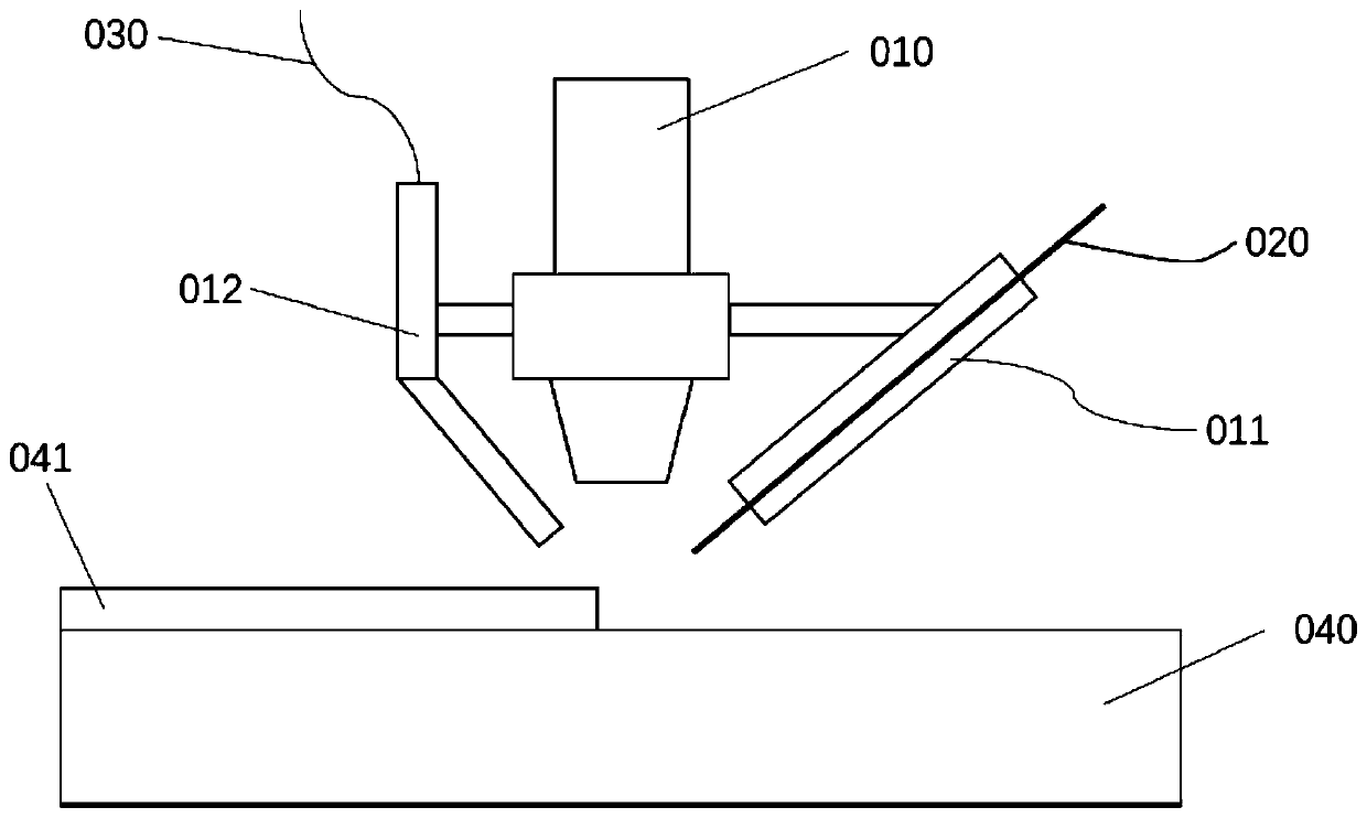
[0027] Such as figure 1 As shown, the composite electron beam additive manufacturing equipment of the present invention includes an electron beam gun 010, a wire feeding nozzle 011, a powder feeding nozzle 012, a metal wire 020, a powder feeding system 030, a forming substrate 040, and a deposition layer 041.

[0028] The wire feeding nozzle 011 and the powder feeding nozzle 012 are installed on the base of the electron beam gun 010, the powder feeding nozzle 012 is connected with the powder feeding system 030, and the metal wire 020 is fed into the wire feeding nozzle 011 through the wire feeder to form a composite electron beam amplifier. material melting system. The base of the electron beam gun 010 is provided with an XYZ three-coordinate movement drive mechanism, and the XYZ three-coordinate movement drive mechanism is connected to the XYZ three-c...


PUM


Abstract

The invention relates to a combined electron beam additive manufacturing device and process. A wire feed spray nozzle and a powder feed spray nozzle are mounted on a base of an electron beam gun of the device, the powder feed spray nozzle is connected with a power feed system, and a metal wire is fed into the wire feed spray nozzle through a wire feeder to form a combined electron beam additive melting system. An XYZ-coordinate movement driving mechanism is arranged on the base of the electron beam gun. The XYZ-coordinate movement driving mechanism is connected with an XYZ-coordinate movementdriving controller. The XYZ-coordinate movement driving controller controls the XYZ-coordinate movement driving mechanism to accurately move the electron beam gun according to the part molding requirements and controls the wire feed spray nozzle and the powder feed spray nozzle to move synchronously to carry out deposition on a required position of a part. The electron beam gun emits an electron beam to melt the surfaces of the metal wire and a molded base plate, and a deposition layer is formed on the surface of the molded base plate after solidification. The combined electron beam additive manufacturing device melts metal powder to be deposited on the surface of the molded base plate to form the deposition layer. Thus, combined additive manufacturing of the part is realized, and the requirements for the manufacturing efficiency and accuracy are met.

Description

technical field [0001] The invention relates to a metal 3D printing device, in particular to an electron beam additive printing device. Background technique [0002] Additive manufacturing, commonly known as 3D printing, is a combination of computer-aided design, material processing and forming technology, based on digital model files, through software and numerical control system, special metal materials, non-metal materials and medical biological materials, according to extrusion, Sintering, melting, light curing, spraying, etc. are accumulated layer by layer to create a manufacturing technology for physical objects. [0003] At present, the main metal 3D printing processes that can be used to directly manufacture metal functional parts include: Selective Laser Sintering (Selective Laser Sintering, SLS) technology, Direct Metal Laser Sintering (Direct Metal Laser Sintering, DMLS), Selective Laser Melting (Selective Laser Sintering) Melting, SLM) technology, Laser Engineer...

Claims


Application Information

Patent Timeline
IPC IPC(8): B22F3/105B33Y30/00B33Y10/00
CPCB33Y30/00B33Y10/00B22F10/00B22F10/25B22F12/46B22F12/37B22F12/55B22F12/53Y02P10/25
Inventor 曹志强沈爱萍
Owner UNIV OF SHANGHAI FOR SCI & TECH
Why Eureka
Try Eureka