

Flue gas denitration device based on liquid oxidizing ions and using method thereof
An oxidizing and flue gas technology, applied in separation methods, chemical instruments and methods, gas treatment, etc., can solve the problems of no disclosed chlorine dioxide generator, low denitration efficiency, etc., and achieve improved oxidation performance, high nitrogen oxides The effect of oxidation rate
- Summary
- Abstract
- Description
- Claims
- Application Information
AI Technical Summary
Problems solved by technology
Method used
Image


Examples
Embodiment 1
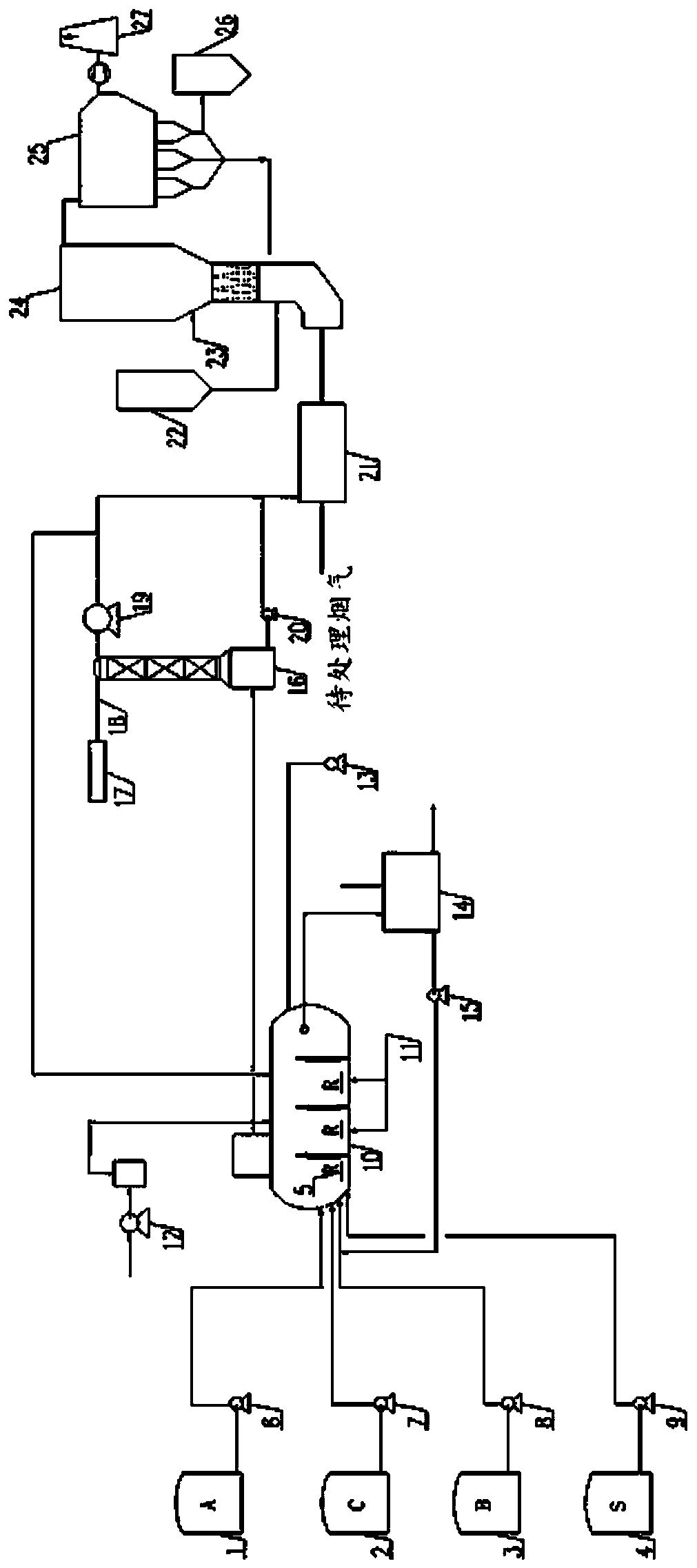
[0101] figure 1 It is a schematic diagram of a flue gas denitrification device of the present invention. The flue gas denitration device of this embodiment includes oxidizing solution production equipment, plasma generation and flue gas oxidation equipment 21, denitrification equipment and dust removal equipment. Oxidizing solution production equipment includes first raw material tank 1, second raw material tank 2, third raw material tank 3, fourth raw material tank 4, reactor 10, blower 12, air compressor 13, mother liquid tank 14, mixed gas absorption equipment 16 and refrigeration equipment 17. The denitration equipment includes an absorbent warehouse 22 , a water supply equipment 23 and a denitration absorption tower 24 . The dust removal equipment includes a dust collector 25 , a by-product bin 26 and a chimney 27 .
[0102] Reactor 10 is a horizontal advection reactor. The interior of the reactor 10 is divided into multiple compartments by at least one partition. A ...
Embodiment 2
[0114] Except for the following settings, the rest are the same as Example 1:
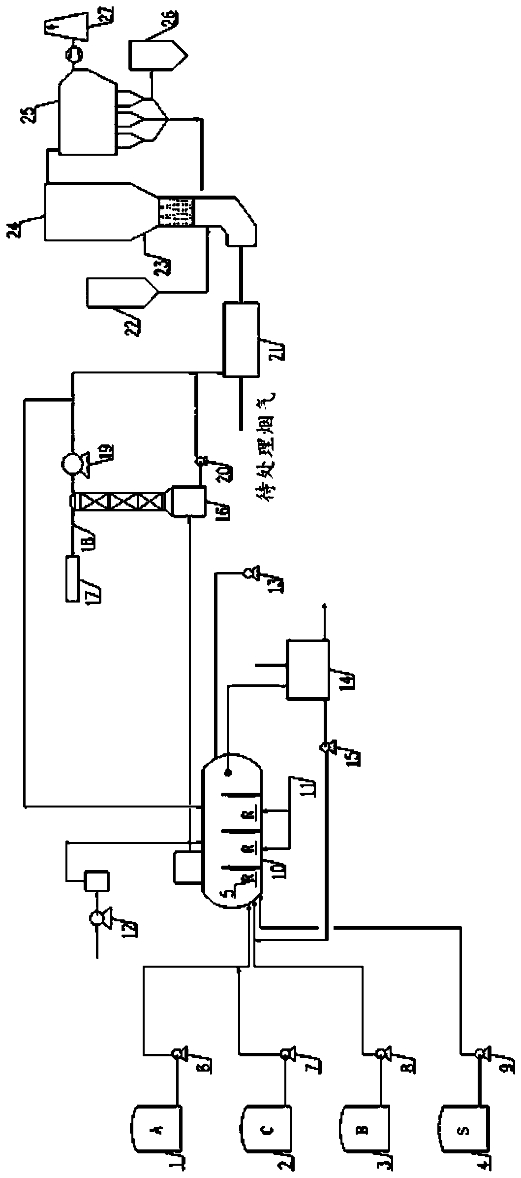
[0115] Such as figure 2 As shown, the side wall of the reactor 10 is provided with a first feed port, a second feed port and a third feed port (not shown). The first raw material tank 1 and the second raw material tank 2 supply material A and material C through the first feed pump 6 and the second feed pump 7 respectively. Material A and material C are mixed and supplied to the reactor 10 through the first feed port. The third raw material tank 3 is connected to the second feed port through the third feed pump 8 , so as to supply the material B to the reactor 10 . The fourth raw material tank 4 is connected to the third feed port through the fourth feed pump 9 , so as to supply the material S to the reactor 10 . This forms a reaction feed solution.
Embodiment 3
[0117] Adopt the denitrification device of embodiment 2 to carry out flue gas denitrification, concrete steps are as follows:
[0118] With the sodium chlorate slurry (material A) from the first raw material tank 1, the hydrogen peroxide (material C) from the second raw material tank 2, the vitriol oil (material B) from the 3rd raw material tank 3 and the 4th raw material tank 4 from The urea (material S) is transported to the reactor 10 to form a reaction feed liquid.
[0119] The reaction feed liquid reacts under the honeycomb catalyst 5 (honeycomb ferric oxide R) arranged in the compartment. The reaction feed liquid in the previous compartment overflows to the next compartment through the baffle tube, thus completing the multi-stage reaction. The heating steam is delivered to the reactor 10 through the steam inlet 11, and the raw material is heated by means of heat exchange. The compressed air from the air compressor 13 is sent to the reaction feed liquid in the reactor 1...
PUM
 Abstract
Description
Claims
Application Information