Manufacturing method of fan blade self-power generation photovoltaic fan

A self-generating and fan technology, applied in photovoltaic power generation, circuits, electrical components, etc., can solve the problems of long charging time, poor use of light, inconvenient movement and other daily needs

Inactive Publication Date: 2020-05-19
山西吕梁孝能移动能源有限公司
View PDF0 Cites 1 Cited by
  • Summary
  • Abstract
  • Description
  • Claims
  • Application Information

AI Technical Summary

Problems solved by technology

The traditional fan must rely on the electric energy provided by fossil energy, and cannot make good use of the sufficient sunlight in summer. The battery charging type fan cannot meet the daily needs well due to factors such as long charging time and inconvenient movement.

Method used


Image

  • Manufacturing method of fan blade self-power generation photovoltaic fan
  • Manufacturing method of fan blade self-power generation photovoltaic fan
  • Manufacturing method of fan blade self-power generation photovoltaic fan

Examples


Embodiment Construction

[0018] specific implementation plan

[0019] composition and structure

[0020] How to make fan blades:

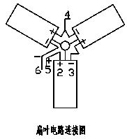
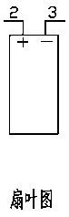
[0021] The thin-film photovoltaic battery chip is deposited on a stainless steel substrate by a PVD magnetron sputtering method to deposit a copper indium gallium selenide power generation film layer, and the upper and lower layers are plated with positive and negative electrodes and cut to form a fan blade type thin film battery chip. The thickness of the chip is Thin and flexible, and the mass-to-power ratio is small to meet the fusion with the fan blades. The fan-blade thin-film battery chip and the copper wire winding are heat-pressed and packaged by leading out wires. The encapsulated thin film chip is hot-pressed with the fan blade receiving piece by hot melt adhesive to form a image 3 The shown fan blades, 2 and 3 are the positive and negative poles of the lead wires.

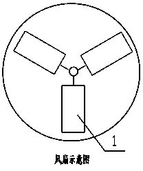
[0022] The fan blade self-generating photovoltaic fan consists of 3 pieces image 3 The fan...


PUM


Abstract

The invention relates to a fan blade self-power generation photovoltaic fan. The photovoltaic fan can use clean light energy, is simple in structure and is placed in a fan protecting shell internally.The movable photovoltaic fan can be achieved without circuits such as an external storage battery. The photovoltaic fan primarily comprises structures of fan blade carrying sheets, a photovoltaic film encapsulating chips which are same in shape with the fan blades and can be adhered to the fan blades, converging wire fixing guide slots fixed to the edge of a rotating shaft of the fan, anodes andcathodes corresponding electric brushes, slide rings corresponding to the electric brushes, slide ring brackets and wires, a fan motor, a fan housing and a base and the like. The photovoltaic fan blade and the photovoltaic film encapsulating chip with an electrode are adhered to form the fan blade; a converging wire of each blade is fixed in the converging wire fixing guide slot after anode and cathode of the film chip are connected in series of each blade; the final anode and cathode terminals are connected to corresponding electric brushes and slide rings; the slide rings are connected to the fan motor through the wires fixed to the brackets; when a current generated by each film chip drives the axis of the fan to rotate by the motor, the converging wires rotate therewith through the electric brushes connected to the fixing guide slots; and the electric brushes rotate on the slide rings to guarantee connection of a circuit to fulfill perfect rotation of the fan. The photovoltaic fansolves the problems that a conventional photovoltaic fan is poor in weak light performance, batteries and storage batteries occupy land, the conventional photovoltaic fan is inconvenient to move and the like.

Description

technical field [0001] The invention relates to a thin-film photovoltaic component chip, which mainly relies on its thinness, flexibility, and low-light characteristics to solve the problem that traditional photovoltaic cells cannot be combined with small daily life components due to rigidity and high mass-to-power ratio. Background technique [0002] 1. The application of photovoltaic modules in daily life is mainly restricted by the characteristics of traditional crystalline silicon modules, such as large mass-to-power ratio, large size, and glass rigidity. The characteristics of flexible thin-film modules can perfectly solve these disadvantages and realize the combination with small fan blades. . [0003] 2. As a must-have in summer, electric fans are active in the daily life of every family, but they will also cause inconvenience due to power supply problems. Traditional photovoltaic fans are moved due to the space occupation of solar cells and batteries. It is also not...

Claims


Application Information

Patent Timeline
Patent Type & Authority Applications(China)
IPC IPC(8): F04D29/26F04D25/08H01L31/0392H01L31/0445
CPCF04D25/08F04D29/26F05D2240/30H01L31/03928H01L31/0445Y02E10/541
Inventor 孙志达侯俊辉赵世恒曹瑞丰姚文玉王强
Owner 山西吕梁孝能移动能源有限公司
Why Eureka
Try Eureka