Fuel cell stack modeling method with fluid non-uniform distribution effect

A fuel cell stack and uniform distribution technology, applied in fuel cells, fuel cell additives, fuel cell control, etc., can solve the problems of small intake manifold size, low computing efficiency, and high computing resource requirements

Active Publication Date: 2020-05-19
TIANJIN UNIV
View PDF6 Cites 20 Cited by
  • Summary
  • Abstract
  • Description
  • Claims
  • Application Information

AI Technical Summary

Problems solved by technology

In terms of experimental research, the main focus is on the measurement of the output voltage and temperature distribution of the single cells in the stack. However, the size of the intake manifold in the stack is small, and the flow sensor cannot be placed in it. Actual gas volume
Numerical simulation methods (such as fluid network models and three-dimensional stack models) can be used to quantitatively analyze the distribution of reaction gases and coolants. Among them, the fluid network model greatly simplifies the heat and mass transfer phenomenon of multi-physical quantity coupling inside the single cell. Therefore, the accuracy of the model is low
The three-dimensional stack model fully considers the flow distribution of the stack manifold and the mass transfer mechanism inside the battery. The accuracy of the model is high, but the demand for computing resources is extremely high and the computing efficiency is low.

Method used


Image

  • Fuel cell stack modeling method with fluid non-uniform distribution effect
  • Fuel cell stack modeling method with fluid non-uniform distribution effect
  • Fuel cell stack modeling method with fluid non-uniform distribution effect

Examples


Embodiment Construction

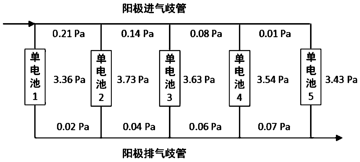
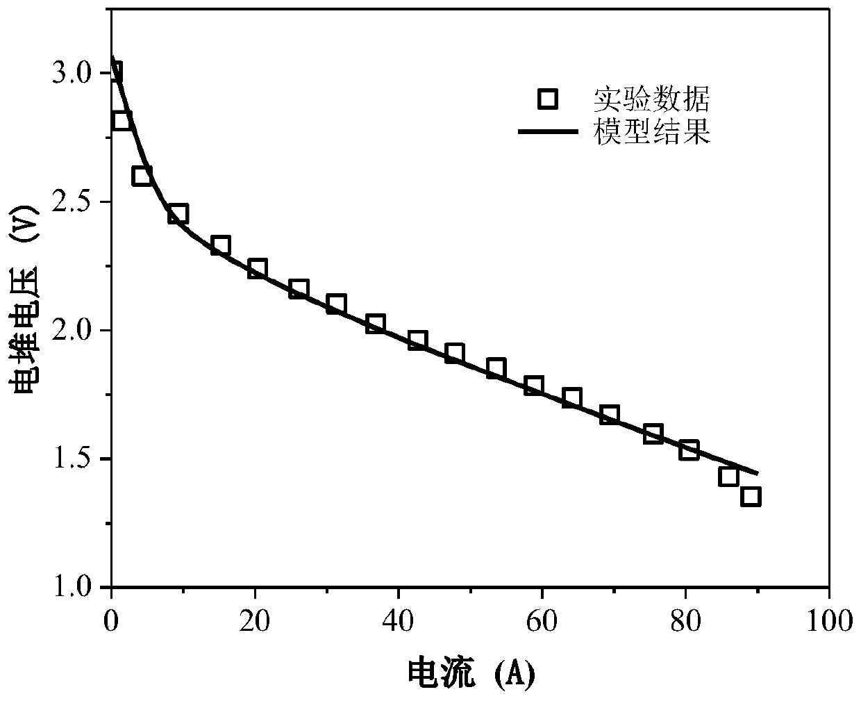
[0106] The method of the invention and the specific steps of building the model will be described in detail below through specific calculation examples.

[0107] Stack structure parameters:

[0108] Single battery quantity: 5; Gas manifold size: 10×6mm; Coolant manifold size: 10×5mm.

[0109] Single battery structural parameters:

[0110] Effective reaction area: 120cm 2 ;Coolant effective heat transfer area: 60cm 2 .

[0111] Plate thickness: 2mm; channel thickness: 1mm; gas diffusion layer thickness: 0.2mm; microporous layer thickness: 0.03mm; catalytic layer thickness: 0.01mm; membrane thickness: 0.0508mm; channel length: 0.1m; Height: 1mm; ratio of runner to rib width: 1.

[0112] Proton exchange membrane density: 1980kg m -3 ;Catalytic layer density: 1000kg m -3 ;Microporous layer density: 1000kg m -3 ;Diffusion layer density: 1000kg m -3 ;Plate density: 1000kg m -3 .

[0113] Proton exchange membrane specific heat capacity: 833J kg -1 K -1 ; Specific heat ca...


PUM

PropertyMeasurementUnit
thicknessaaaaaaaaaa
thicknessaaaaaaaaaa
thicknessaaaaaaaaaa

Abstract

The invention discloses a fuel cell stack modeling method with a fluid non-uniform distribution effect. Establishment of a model comprises three parts: a fluid network model, a single cell mechanism model and coupling of the fluid network model and the single cell mechanism model, wherein the fluid network model is used for calculating the pressure drop loss of each part to obtain the actual flowof gas flowing into each single cell and the actual distribution condition of the cooling liquid; the single cell mechanism model calculates the membrane water content, the liquid water volume fraction, the gas components, the temperature and the like at the center of each layer, and can reflect the gas concentration and the temperature distribution in each single cell; and through coupling of thetwo models, the distribution condition of the reaction gas in the electric pile can be accurately calculated, and meanwhile, an electric pile model of the internal parameter distribution condition ofeach single cell can be provided. According to the method, the defect of low model accuracy caused by excessive simplification of a previous fluid network model on a heat and mass transfer mechanismin each single cell is overcome, and the problem of low simulation efficiency of the three-dimensional galvanic pile model is also solved.

Description

technical field [0001] The invention belongs to the field of proton exchange membrane fuel cells, and in particular relates to a proton exchange membrane fuel cell stack modeling method having the effect of non-uniform distribution of fluids such as intake air and cooling liquid. Background technique [0002] Proton exchange membrane fuel cell (PEMFC) has the advantages of high energy density, high energy conversion efficiency, low operating temperature and zero emission, and can be used as one of the clean energy sources in the future transportation industry. As the core component of the system, the fuel cell stack converts the chemical energy of the reaction gas into electrical energy. Due to the limited output voltage and power of the single cell, the fuel cell stack is usually composed of dozens or even hundreds of single cells connected in series (or in parallel). To meet the output voltage and power requirements. [0003] After the reaction gas (such as hydrogen, air)...

Claims


Application Information

Patent Timeline
Patent Type & Authority Applications(China)
IPC IPC(8): H01M8/04298H01M8/04992H01M8/2457
CPCH01M8/04305H01M8/04992H01M8/2457Y02E60/50
Inventor 杜青杨子荣焦魁
Owner TIANJIN UNIV
Why Eureka
Try Eureka