
Gravity power generation and traction power generation system and power generation method thereof

A technology of gravity power generation and power generation device, which is applied in the directions of engines, machines/engines, and mechanical power generated by physical force, which can solve the problems of inability to achieve continuous power generation and inability to judge the size of the mass of suspended heavy objects, and achieve simple and reduced structure. The effect of loss, easy disassembly and assembly

Pending Publication Date: 2020-05-22
NINGBO UNIV
View PDF1 Cites 1 Cited by
  • Summary
  • Abstract
  • Description
  • Claims
  • Application Information

AI Technical Summary

Problems solved by technology

Two: The existing gravity generators can only generate electricity by hanging heavy objects and doing work by gravity in a single time, and cannot achieve continuous power generation
However, the system cannot use the force sensor to judge the mass of the suspended weight, which corresponds to the suitable grade of the mainspring, and then generate electricity. It cannot also be combined with the sprocket and chain device to achieve manual cycle pulling and continuous power generation.

Method used


Image

  • Gravity power generation and traction power generation system and power generation method thereof
  • Gravity power generation and traction power generation system and power generation method thereof
  • Gravity power generation and traction power generation system and power generation method thereof

Examples


Embodiment Construction

[0053] The present invention will be described in detail below in conjunction with specific embodiments. The following examples will help those skilled in the art to further understand the present invention, but do not limit the present invention in any form. It should be noted that those skilled in the art can make several changes and improvements without departing from the concept of the present invention. These all belong to the protection scope of the present invention.

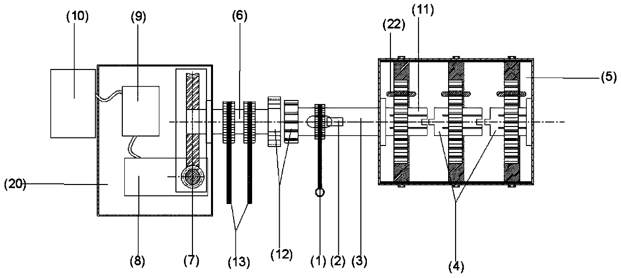
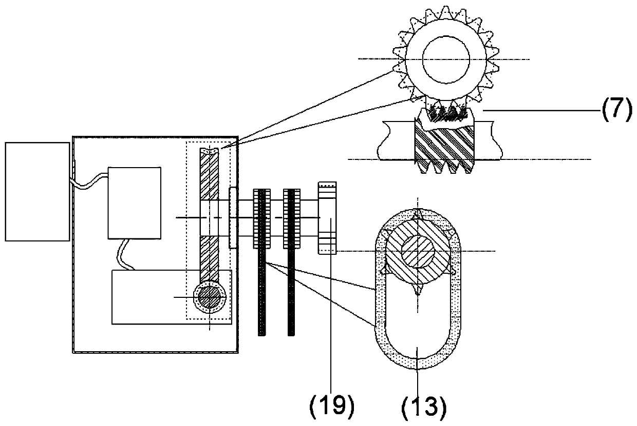
[0054] The invention provides a gravity power generation and traction power generation system and a power generation method thereof, which specifically include a force sensor 2, a first power transmission shaft 3, a second power transmission shaft 6, a multi-stage electric barrel device, a multi-stage electric generator The clockwork spring 17 in the crate device is covered with an electrified insulator 18, a shaft coupling 12, a sprocket chain mechanism 13, a worm and gear speed changer 7, a generator 8...


PUM


Abstract

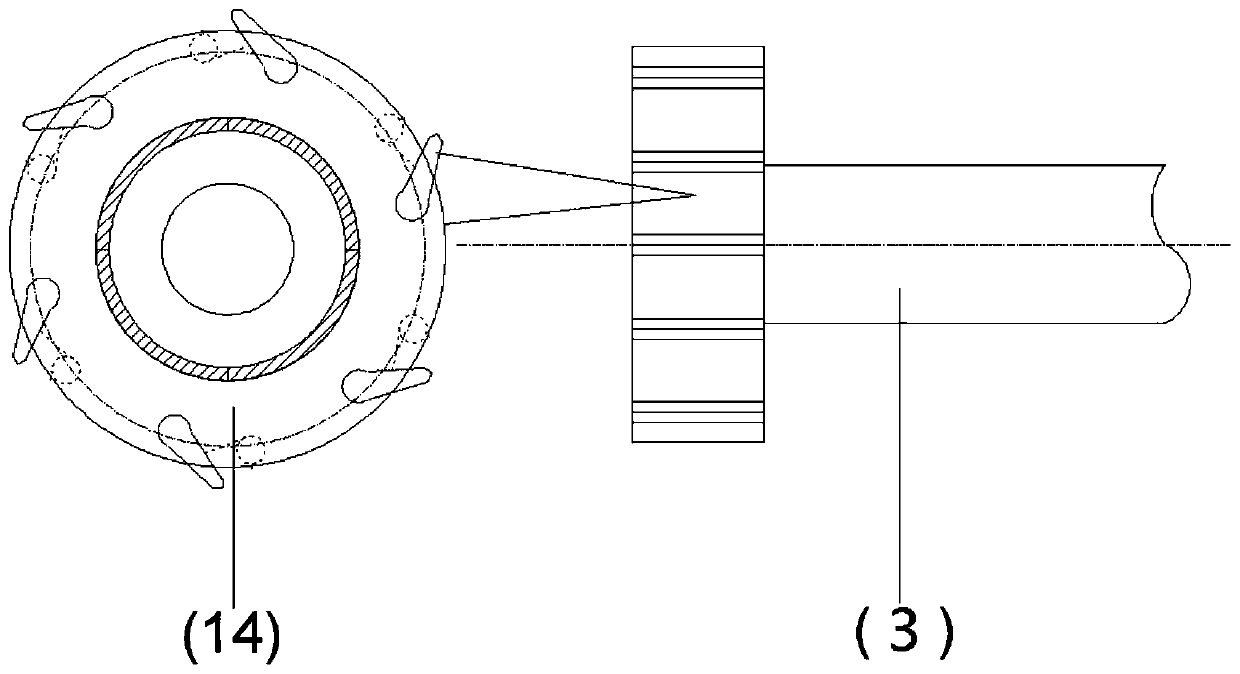
The invention provides a gravity power generation and traction power generation system and a power generation method thereof. The gravity power generation and traction power generation system comprises a gravity power generation device, a traction power generation device, a power generation current stabilization and storage device and a coupler (12); the gravity power generation device is connected with the traction power generation device through the coupler (12), and the traction power generation device is connected with the power generation current stabilization and storage device; and thecoupler (12) comprises a ratchet wheel (14) and a ratchet-shaped concave chamber (19), the ratchet wheel (14) is connected with the gravity power generation device, the ratchet-shaped concave chamber(19) is connected with the traction power generation device, and the ratchet wheel (14) and the ratchet-shaped concave chamber (19) are connected to form one-way meshing transmission. According to thegravity power generation and traction power generation system and the power generation method thereof, the structure is simple, operation is convenient, power generation can be conducted through twomodes including the gravitational potential energy effect or traction, the power generation capacity is guaranteed, and the gravity power generation and traction power generation system has the advantages of being low in manufacturing cost, long in equipment life and easy to disassemble, assembly and maintain.

Description

technical field [0001] The present invention relates to the field of clockwork spring power generation, in particular, to a gravity power generation and traction power generation system and its power generation method, especially to an intelligent identification of heavy objects that can be converted into electric energy through gravitational potential energy and take into account the manual cycle pulling through the transmission shaft System and method for rotating power generation. Background technique [0002] There are two relatively big problems in the existing gravity generators. One: when generating electricity by hanging heavy objects, the quality of the heavy objects that can be selected is limited to a small range. In the case where the rotational torque cannot be input to the mainspring, when the mass of the heavy object is large, the problem of overload will occur, which will directly cause damage to the energy storage device such as the spring. The efficiency o...

Claims


Application Information

Patent Timeline
Patent Type & Authority Applications(China)
IPC IPC(8): F03G3/00F03G5/00
CPCF03G3/00F03G5/00
Inventor 吴兆波邓琰黄焜安劳静文齐斌曹均李淑欣文静波
Owner NINGBO UNIV
Learn More