Metal lithium battery

A metal lithium and battery technology, applied in the field of metal lithium batteries, can solve the problems of reducing the utilization rate of negative electrode active materials, reducing battery capacity, etc., achieving high electrical effect and heat dissipation effect, increasing reaction area, and increasing the effect of utilization rate.

Active Publication Date: 2020-05-22
EVE ENERGY CO LTD
View PDF15 Cites 0 Cited by
  • Summary
  • Abstract
  • Description
  • Claims
  • Application Information

AI Technical Summary

Problems solved by technology

[0004] However, the current collector part covered on the negative electrode sheet will prevent the electrolyte from reacting with the active material on t

Method used


Image

  • Metal lithium battery
  • Metal lithium battery
  • Metal lithium battery

Examples


Embodiment 1

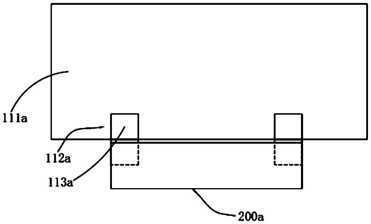
[0054] see figure 2 , is a schematic diagram of a partial structure of a metal lithium battery according to Example 1 of the present invention, the current collector 112a includes two current collectors 113a, and the two current collectors 113a are located on the opposite side edges of the negative electrode tab 200a In this way, the distance between the two current collectors 113a can be maximized, and the heat generation is at the intersection of the current collectors 113a, lithium pole pieces 111a and negative electrode tabs 200a, so that the two current collectors The fluid 113a is located at the opposite side edges of the negative tab 200a, thereby maximizing the distance between the two heat sources, effectively reducing local overheating, and improving battery safety and electrical performance.

[0055] Further, the two current collectors are arranged symmetrically with respect to the central axis of the lithium pole piece, so that the transfer path of the charge of t...

Embodiment 2

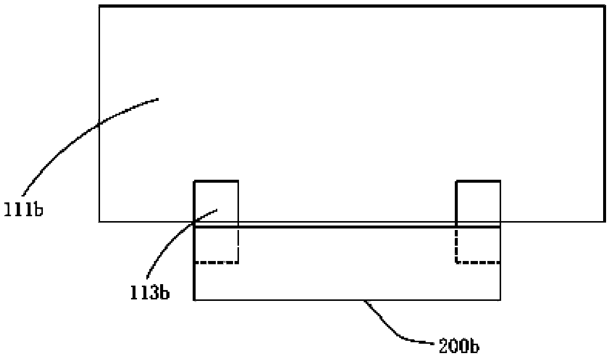
[0061] see image 3 , is a schematic diagram of a partial structure of a metal lithium battery in Example 2 of the present invention, the lithium pole piece 111b has a long side and a short side, and each of the current collectors 113b is electrically connected to the long side of the lithium pole piece 111b, respectively, The distance between the current collector 113b and the active material on the lithium pole piece 111b can be reduced, so that the active material of the lithium pole piece 111b can be fully utilized, the utilization rate of the negative electrode active material is improved, the battery capacity is improved, and the charge of the battery The transmission path is more reasonable, which can reduce the internal resistance of the battery and reduce the heating problem.

Embodiment 3

[0063] see Figure 4 , is a schematic diagram of a partial structure of a metal lithium battery according to Example 3 of the present invention, the current collector 112c includes two current collectors 113c, and the two current collectors 113c are located on the opposite side edges of the negative electrode tab 200c The current collector 112c includes an angled piece 114c and a main piece 115c, and the angled piece 114c is connected to the main piece 115c. In actual processing, the angled piece 114c and the main piece 115c are integrally formed; the two current collectors 112c, the extension direction of the angled piece 114c forms an included angle, and the degree of the included angle is between 0 degrees and 180 degrees. In this way, the distance between the two positions that generate heat sources can be further increased, and the heat can be more effectively alleviated. Local overheating problem, improve battery safety performance and electrical performance.


PUM


Abstract

A metal lithium battery comprises a battery cell and a negative pole lug, the battery cell comprises a negative pole piece monomer, a positive pole piece monomer and a diaphragm piece, the negative pole piece monomer comprises a lithium pole piece and a current collector electrically connected with the lithium pole piece, the current collector comprises a plurality of current collectors, and eachcurrent collector is electrically connected with the lithium pole piece. Therefore, the accumulated area of each current collector can be further smaller than the area of the traditional monolithic current collector, and the accumulated weight of each current collector is smaller than the weight of the traditional monolithic current collector, so that the utilization rate of the negative active material can be further improved, and the battery capacity can be further improved.

Description

technical field [0001] The invention relates to the technical field of lithium batteries, in particular to metal lithium batteries. Background technique [0002] For metal lithium batteries, especially for laminated lithium batteries, the cells include a plurality of alternate and stacked pole pieces and multiple separators, that is, every two pole pieces sandwich a separator, wherein the pole piece includes a negative electrode The electrode sheet and the positive electrode sheet, through the contact of each electrode sheet with the electrolyte, complete the electrochemical reaction and realize the battery function. As for the prismatic winding battery, it includes a positive electrode sheet in the form of a belt, a negative electrode sheet and a separator between the two. [0003] For the negative pole piece, it will be connected to the negative pole tab through the whole piece of current collector, and the whole piece of current collector is connected to the negative pol...

Claims


Application Information

Patent Timeline
IPC IPC(8): H01M10/0587H01M10/052H01M4/13
CPCH01M4/13H01M10/052H01M10/0587Y02E60/10Y02P70/50
Inventor 赖彩婷何兰星袁中直
Owner EVE ENERGY CO LTD
Why Eureka
Try Eureka