
Boiler capable of improving SNCR reaction efficiency

A reaction efficiency and boiler technology, applied in the field of boilers that can improve the SNCR reaction efficiency, can solve the problems of reducing the flue gas temperature, restricting the SNCR denitration reaction efficiency, etc., and achieve the effect of improving the reaction efficiency

Pending Publication Date: 2020-05-26
HUANENG CLEAN ENERGY RES INST
View PDF0 Cites 0 Cited by
  • Summary
  • Abstract
  • Description
  • Claims
  • Application Information

AI Technical Summary

Problems solved by technology

For traditional PC boilers, the hot flue gas passes through the high pass, low pass, economizer, etc. from the furnace outlet in order to quickly reduce the flue temperature; for the traditional CFB boiler, the flue gas also passes through the high pass, low pass, Economizer and other heating surfaces, the common feature of both is that the area available for SNCR reaction in the flue is very short, and even there is no reaction time after the flue gas is mixed with the reducing agent, which restricts the improvement of SNCR denitrification reaction efficiency. This factor is also difficult for SNCR The main reasons for the application of PC boilers

Method used


Image

  • Boiler capable of improving SNCR reaction efficiency
  • Boiler capable of improving SNCR reaction efficiency

Examples


Embodiment Construction

[0020] In order to make the purpose, technical solutions and advantages of the embodiments of the present invention clearer, the technical solutions of the present invention will be clearly and completely described below in conjunction with the accompanying drawings. Obviously, the described embodiments are part of the embodiments of the present invention, not all of them. the embodiment. Based on the embodiments of the present invention, all other embodiments obtained by persons of ordinary skill in the art without making creative efforts belong to the protection scope of the present invention.

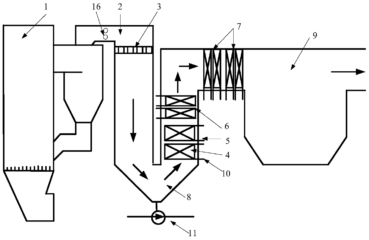
[0021] Such as figure 1 As shown, a boiler that can improve the reaction efficiency of SNCR includes a boiler 1 and a tail flue 2, the flue gas outlet of the boiler 1 is connected to the inlet of the tail flue 2, and the outlet of the tail flue 2 is connected to the dust collector 9; the tail flue 2 Along the medium flow direction, it includes a descending section and an ascending s...


PUM


Abstract

The invention discloses a boiler capable of improving SNCR reaction efficiency. The boiler comprises the boiler and a backpass, a flue gas outlet of the boiler is in communication with an inlet of thebackpass, and an outlet of the backpass is in communication with a dust remover; the backpass comprises a descending section and an ascending section in the medium flowing direction, the descending section and the ascending section communicate at the bottom of the backness, a SNCR reducing agent spray gun and a flow equalizing device are arranged at the inlet of the backpass in the medium flowingdirection, a heat-absorbing surface is arranged in the ascending section, and the flue gas flows through a heat insulation space of the descending section of the backpass after passing through an outlet of a furnace. By optimizing the arrangement of the heat-absorbing surface, so that the space can be within the SNCR reaction window temperature range, and meanwhile, it is guaranteed that SNCR hassufficient reaction time; a high-temperature superheater in the ascending section is arranged at the lowermost layer, so that the use amount of main steam pipeline metal material can be saved to themaximum extent, and the investment cost can be saved; the flue gas in the ascending section flows from bottom to top, dust accumulation can be avoided, and the boiler soot blowing operation cost can be saved.

Description

technical field [0001] The invention belongs to the technical field of thermal power boilers, and in particular relates to a boiler capable of improving SNCR reaction efficiency. Background technique [0002] Selective non-catalytic reduction reaction (SNCR) denitrification is one of the mainstream technologies for nitrogen oxide removal in thermal power plants. Its reaction temperature window is 850-1050°C. The presence of the separator greatly improves the denitrification efficiency of the CFB boiler compared with the pulverized coal boiler, up to about 80%. In recent years, the pressure of environmental protection has been increasing, and higher requirements have been put forward for the SNCR denitrification efficiency of boilers. The important factors affecting the SNCR denitrification efficiency of CFB boilers are whether the reducing agent is atomized and mixed with high-temperature flue gas sufficiently, and whether the reaction temperature meets the conditions. Whet...

Claims


Application Information

Patent Timeline
Patent Type & Authority Applications(China)
IPC IPC(8): F23C10/18F23L15/04F22G3/00F23J15/02F23J15/06
CPCF22G3/00F23C10/18F23J15/022F23J15/06F23L15/04Y02E20/34
Inventor 李楠刘海峰张世鑫史磊
Owner HUANENG CLEAN ENERGY RES INST
Learn More