Two-stage heating pretreatment system for preparing solid gas-phase reactant

A phase reaction, solid gas technology, applied in chemical/physical processes, gas generating devices, chemical instruments and methods, etc., can solve the problems of difficult control of solid material flow, complex temperature, energy change, etc., and achieve easy maintenance and easy maintenance. Controllable effect of processing and material phase change

Pending Publication Date: 2020-05-29
TIANJIN UNIV
View PDF0 Cites 2 Cited by
  • Summary
  • Abstract
  • Description
  • Claims
  • Application Information

AI Technical Summary

Problems solved by technology

[0005] At present, the means of preparing gas-phase reactants with liquid substances is relatively mature. How to make good use of the technical basis and technical ideas of liquid substances to overcome the difficulty in controlling the flow of solid substances after liquefaction and gasification, the energy changes in solid-liquid and liquid-gas processes, and the The problem of complex temperature is required, and at the same time, taking into account the problem of sample injection pressure and temperature setting and maintenance, a pretreatment system for preparing solid gas phase reactants with stable sample injection, controllable flow rate and controllable phase change is developed. The problem to be solved by the present invention

Method used


Image

  • Two-stage heating pretreatment system for preparing solid gas-phase reactant
  • Two-stage heating pretreatment system for preparing solid gas-phase reactant
  • Two-stage heating pretreatment system for preparing solid gas-phase reactant

Examples


Embodiment Construction

[0034] The present invention will be further described below in conjunction with the accompanying drawings and specific embodiments, but the following embodiments in no way limit the present invention.

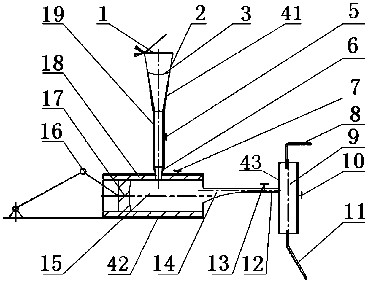
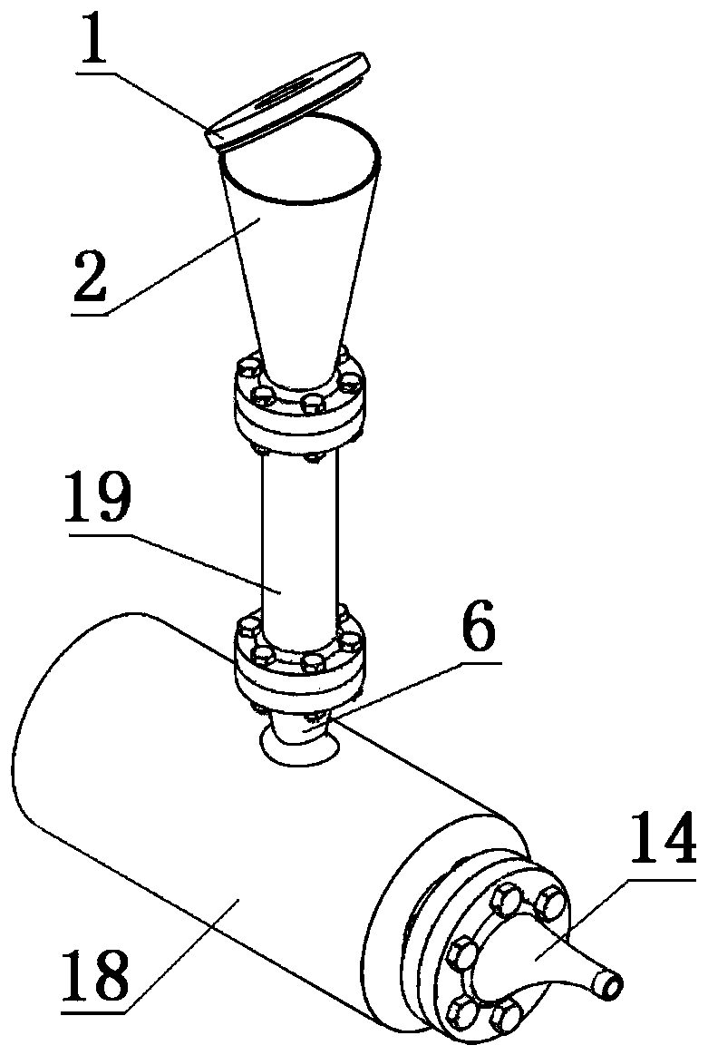
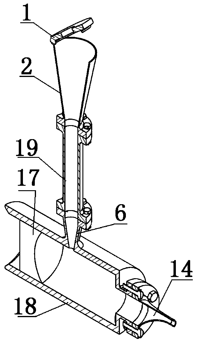
[0035] Such as figure 1 , figure 2 and image 3 As shown, a two-stage heating pretreatment system for preparing solid gas phase reactants proposed by the present invention includes a solid-liquid phase change device, a liquid-gas phase change device and a carrier gas tank 9 .

[0036] The solid-liquid phase change device includes a cylindrical body, which includes a horn tube 2, a straight tube 19 and a conical tube 6 connected in sequence from top to bottom in the axial direction, and the horn tube 2, the straight tube 19 and the conical tube 6 The barrel 6 is connected with flanges and bolts in turn, and seals are provided at the joints. The upper end of the cylinder body is provided with a sampling cover 1, the sampling cover 1 is hinged with the edge of the trumpet 2, ...


PUM


Abstract

The invention discloses a two-stage heating pretreatment system for preparing a solid gas-phase reactant. The two-stage heating pretreatment system comprises a solid-liquid phase change device, a liquid-gas phase change device and a gas carrier tank. The solid-liquid phase change device comprises a horn-shaped barrel, a straight barrel and a conical barrel which are sequentially communicated fromtop to bottom in the axial direction, the horn-shaped barrel is provided with a sample injection cover, a squint window made of tempered glass is embedded in the sample injection cover, and a concaveelectric heating metal net is arranged in the horn-shaped barrel. The liquid-gas phase change device comprises a cylinder with an open end, a piston is arranged in an inner cavity of the cylinder, andthe piston is driven by a crank-link mechanism driven by a motor to do reciprocating motion. The other end of the cylinder is sequentially connected with a steel section gradient pipe and a steel gasguide pipe, the steel gas guide pipe is connected with a needle valve, a pressure sensor and a flow meter, and the steel gas guide pipe is connected to a carrier gas tank. An inner cavity of the liquid-gas phase change device is communicated with the conical barrel. The problems of abnormal liquefaction, gas-phase and liquid-phase reactant mixing, pressure difference before and after treatment ofthe device and overlarge temperature difference can be effectively avoided.

Description

technical field [0001] The invention belongs to the field of burners and relates to a fuel preheating device, an evaporating device and a device for controlling fuel feeding on the evaporator. Background technique [0002] Since the 1950s, the experimental equipment in the field of combustion chemistry and internal combustion engine combustion has undergone several generations of updates and has made great progress. Today, combustion research (including fuel thermal decomposition, oxidation, and combustion flame research) generally uses experimental equipment such as flow reactors, shock tubes, constant volume incendiary bombs, and fast compressors combined with mass spectrometry, chromatography, and other analytical methods. Application and equipment research, related research using these equipment has the advantages of simple preparation of reactants, relatively mature technology, easy maintenance, and convenient data acquisition. Among them, the flow reactor is one of th...

Claims


Application Information

Patent Timeline
Patent Type & Authority Applications(China)
IPC IPC(8): B01J7/00
CPCB01J7/00
Inventor 贺泳迪夏然宋金瓯
Owner TIANJIN UNIV
Why Eureka
Try Eureka