
Constant-temperature structure for high-performance gas detection device and preparation method

A gas detection, high-performance technology, applied in the field of sensors, can solve the problems of affecting the degree of sensitivity and the sensitivity of sensing signals, changes in electrical and physical properties, and small gas sensing area, so as to facilitate miniaturization, improve sensitivity, and detect sensitive effect

Pending Publication Date: 2020-05-29
CHINA POWER CONSRTUCTION GRP GUIYANG SURVEY & DESIGN INST CO LTD
View PDF0 Cites 0 Cited by
  • Summary
  • Abstract
  • Description
  • Claims
  • Application Information

AI Technical Summary

Problems solved by technology

However, the gas detection device with this structure has the following problems: the gas sensitive resistor is only a single-layer surface, and the sensing area for the gas is very small, which affects the sensitivity and the sensitivity of the sensing signal; at the same time, the entire device works in a natural environment. As the temperature changes, the electrical and physical properties of each component will change to a certain extent, which will affect the detection accuracy
At the same time, when some limiting devices are used in high-reliability environments or in some special fields such as aerospace, aviation, ships, precision instruments, geological exploration, oil exploration, other field operations, communications, industrial control and other environments with complex temperature changes, in order to To ensure the accuracy of detection, it is necessary to add some bulky and expensive ambient temperature control devices for use
On the other hand, due to the strong temperature selectivity of gas sensitive resistors for different gases, it is necessary to set different working environment temperatures for different detection gases, which brings great inconvenience to the use of the device.

Method used


Image

  • Constant-temperature structure for high-performance gas detection device and preparation method
  • Constant-temperature structure for high-performance gas detection device and preparation method

Examples


Embodiment Construction

[0028] The present invention will be further described below in conjunction with the accompanying drawings and embodiments, but not as a basis for limiting the present invention.

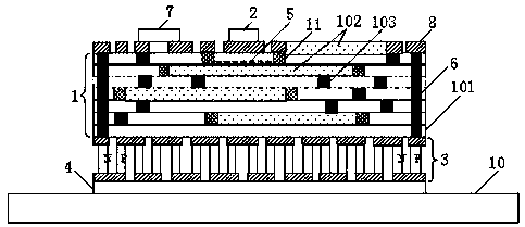
[0029] Example. A constant temperature structure for a high-performance gas detection device, consisting of figure 2 shown, including top Al 3 N 4 Substrate unit 1, top layer Al 3 N 4 The lower surface of the substrate unit 1 is integrated with the TEC unit 3, and the lower surface of the TEC unit 3 is integrated with the underlying Al 3 N 4 Substrate 4; The top layer Al 3 N 4 The substrate unit 1 consists of more than one layer of perforated Al 3 N 4 The substrates 101 are stacked in the vertical direction, and each layer is perforated with Al 3 N 4 Thin-film gas-sensitive resistors 102 are integrated on the substrate 101, and each layer is perforated with Al 3 N 4 The via holes of the substrate 101 are all filled with fillers 103; 3 N 4 The second layer from the top layer of substr...


PUM

PropertyMeasurementUnit
Thicknessaaaaaaaaaa
Thicknessaaaaaaaaaa

Abstract

The invention discloses a constant-temperature structure for a high-performance gas detection device and a preparation method. The structure comprises a top layer Al3N4 substrate unit, and a TEC unitis integrated on the lower surface of the top layer Al3N4 substrate unit. The top layer Al3N4 substrate unit is formed by stacking more than one layer of perforated Al3N4 substrate in the vertical direction, a thin film gas sensitive resistor is integrated on each layer of perforated Al3N4 substrate, and a via hole of each layer of perforated Al3N4 substrate is filled with a filler. Thick-film thermistors are further embedded in the second layer of punched Al3N4 substrate which is located on the top layer of the top layer Al3N4 substrate unit and faces inwards. The N-type semiconductor and theP-type semiconductor are respectively arranged at two ends of the TEC unit and are connected to the surface bonding region through a channel structure formed by via holes. The thick film thermistor is connected with a controllable bidirectional switch circuit for controlling the current direction of the TEC unit. The temperature drift range of related performance parameter indexes of all components in the gas sensitive device can be reduced, and miniaturization of assembly is facilitated.

Description

technical field [0001] The invention relates to the technical field of sensors, in particular to a constant temperature structure and a preparation method for a high-performance gas detection device. Background technique [0002] The structure of traditional gas detection devices is mainly to directly mount and paste discrete components such as sensing signal processing chips, gas sensitive resistors, and other active / passive components on aluminum nitride ceramic substrates (Al 3 N 4 ), and then perform circuit welding to complete the circuit connection. Its structure is as follows figure 1 shown. However, the gas detection device with this structure has the following problems: the gas-sensitive resistor is only a single-layer surface, and the sensing area for gas is very small, which affects the sensitivity and the sensitivity of the sensing signal; at the same time, the entire device works in a natural environment. As the temperature changes, the electrical and physica...

Claims


Application Information

Patent Timeline
IPC IPC(8): G01N27/12H01L49/02
CPCG01N27/125H10N97/00
Inventor 张昱昕
Owner CHINA POWER CONSRTUCTION GRP GUIYANG SURVEY & DESIGN INST CO LTD
Learn More